Foundation Settlement: How to Calculate It and Tolerable Limits

A footing can pass the bearing capacity check and still be a failure. Bearing capacity is the ultimate limit state: the soil either holds or it does not. Settlement is the serviceability limit state, and it fails long before capacity does whenever the footing sits on clay, silt, or any soil that compresses under load.
This article covers the two things you actually need to size a footing: how to calculate the settlement, and how much settlement the structure can tolerate. The worked example at the end runs a complete calculation with real numbers, so you can follow every step and reproduce it in a spreadsheet.
Units: values are given in SI with U.S. customary equivalents in parentheses, since this blog serves both systems. The formulas themselves use SI so the math works out cleanly.
Why settlement, not bearing capacity, controls most designs
Bearing capacity tells you the pressure at which the soil fails in shear. Settlement tells you how much the footing sinks at pressures well below failure. For a square footing in a medium-dense sand, the allowable bearing pressure is about 200-300 kPa (≈ 4-6 ksf) for a 25 mm (≈ 1 in) settlement limit, while the ultimate capacity would carry several times that. You hit the settlement limit first.
Two rules of thumb that hold across most of practice:
- Sands and gravels: bearing capacity usually controls, because settlement happens immediately as the load goes on and stops. A footing that takes the load is a footing that has settled.
- Clays and silts: settlement almost always controls. The same footing settles gradually over months or years as pore water drains, and the total can reach tens of millimeters even when the factor of safety against bearing failure is 3 or more.
This is why a geotechnical report gives you an allowable bearing pressure derived from a settlement criterion, not from ultimate capacity. If you want the full derivation of the capacity side, gross vs net bearing pressure covers the limit state that capacity checks use.
The three components of settlement
Total settlement under a footing is the sum of three independent mechanisms:
| Component | Soil | When | Typical magnitude |
|---|---|---|---|
| Immediate (elastic) | Sands, gravels, stiff clays | As load is applied | Small to moderate |
| Consolidation (primary) | Clays, silts | Months to years | Often the largest |
| Secondary (creep) | Organic clays, peat | Years to decades | Can dominate in peat |
Immediate settlement
The elastic deformation of the soil skeleton, without volume change. In sands it happens during construction because water drains instantly; in stiff clays it happens at constant volume as the soil distorts laterally.
Primary consolidation
The volume change that occurs as pore water is squeezed out of a saturated clay. It is the component that takes months or years and produces the classic slow sinking of buildings. The mathematics behind the rate is the one-dimensional consolidation theory of Terzaghi (1923), and the magnitude is governed by the compression index and the stress history of the clay.
Secondary settlement
Creep of the soil skeleton under constant effective stress, after pore pressures have dissipated. It is small in inorganic clays and dominant in peat and highly organic soils, where it can continue for decades. The creep component over a time interval is
with the secondary compression index (about 0.005-0.02 in inorganic clays, higher in organic soils and peat) and , the times since loading.
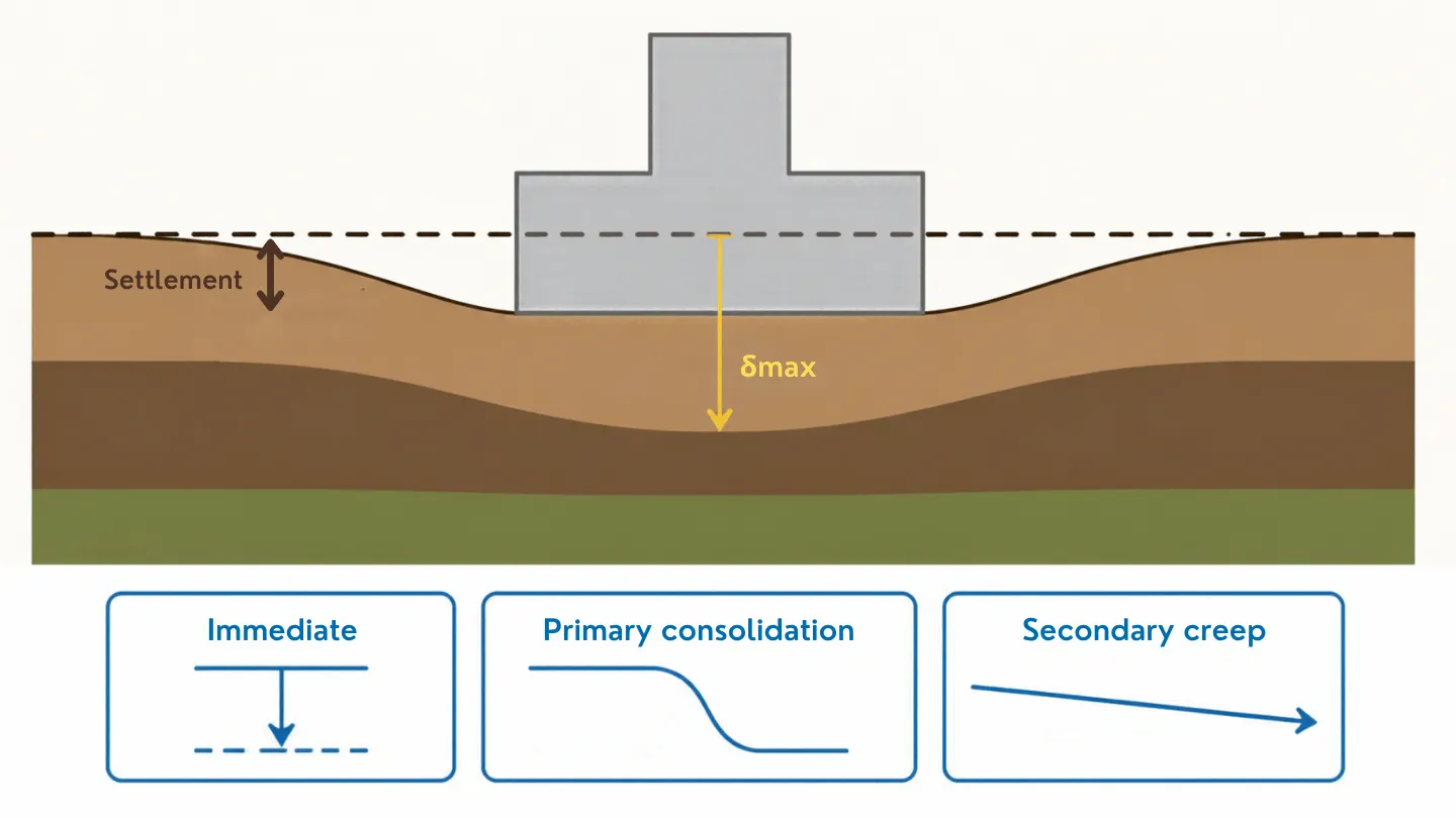
The three components plot as distinct shapes against log time: the immediate part is a near-vertical jump as the load goes on, primary consolidation is the S-shaped branch that flattens toward its asymptote, and secondary creep continues as a shallow straight line that never quite levels off. A settlement that looks “done” after construction is usually only done with its immediate component.
How much settlement is too much: tolerable limits
The tolerable settlement depends on the structure, not on the soil. A storage tank can tolerate 100 mm of uniform settlement; a masonry building with rigid partitions cracks at a fraction of that.
Two quantities matter:
- Total settlement — the absolute sinking of the footing. It matters when it connects to rigid services, adjacent structures, or access requirements.
- Differential settlement — the difference in settlement between two footings (or between the ends of one footing). This is what cracks structures, because it distorts the frame.
The classic damage thresholds, from the work of Skempton and MacDonald (1956) and refined by Bjerrum (1963) and Burland et al. (1977), are expressed as the angular distortion , the differential settlement between two points divided by the distance between them:
| Angular distortion | Effect |
|---|---|
| 1/1000 (0.001) | Limit for sensitive structures, machinery, and some codes’ cracking threshold |
| 1/500 (0.002) | Commonly used design limit for buildings before cracks appear |
| 1/300 (0.003) | First cracking in load-bearing walls (Skempton & MacDonald) |
| 1/150 (0.007) | Structural damage |
Most design codes work with a safe limit of for ordinary buildings, and or tighter for structures with sensitive finishes or machinery.
For total settlement, practice references a few benchmark numbers:
- 25 mm (≈ 1 in): the classic allowable settlement used by the Meyerhof and Bowles correlations for footings on sand. It is a design criterion, not a damage limit.
- 65 mm (≈ 2.5 in): the maximum tolerable settlement for isolated footings in clay in the Skempton & MacDonald study.
- 89 mm (≈ 3.5 in): the figure most often quoted for rafts on clay, at the upper end of the 65-100 mm range that practice cites as tolerable for rafts.
Eurocode 7 (EN 1997-1) deliberately does not fix a single number: Annex H gives indicative values and leaves the limit to the designer based on the structure’s sensitivity. The limit you adopt should come from the structure, not from a default.
Immediate settlement in sand: the elastic method
For a footing on sand or other coarse soil, immediate settlement happens during construction and can be estimated with the elastic half-space solution:
with the net applied pressure, the footing width, the soil modulus, Poisson’s ratio, and an influence factor that depends on footing shape and rigidity. For a square footing, ; a long strip settles noticeably more per unit width, with at rising to about for very long strips () (rigid-footing influence factors after Bowles, 1988, Table 13.4).
The elastic estimate is a screening tool. It is only as good as the modulus you feed it, and in sand is notoriously variable: SPT and CPT correlations give values that scatter by a factor of two. For design, the method of Schmertmann (1970), as modified by Schmertmann, Hartman and Brown (1978), is the standard refinement for sands:
where and are correction factors for embedment and time, and is a strain influence factor that starts at 0.1 at the footing base, peaks at below square footings and at depth below strips (), and returns to zero at (squares) or (strips), per Schmertmann, Hartman and Brown (1978). The simplified peak value is , with the effective vertical stress at the peak depth.
Consolidation settlement in clay: the one-dimensional method
For saturated clays, the magnitude of primary consolidation settlement is computed with the one-dimensional method (Terzaghi and Peck, in the form used by every geotechnical text):
where is the thickness of the compressible layer, its initial void ratio, the compression index, the initial effective vertical stress at the middle of the layer, and the final effective stress after the footing load is applied.
The catch is stress history. If the clay is overconsolidated and the final stress stays below the preconsolidation pressure , the soil moves along the much flatter recompression line and you use (the recompression index, typically 5-10 times smaller than ):
Using when the clay is truly overconsolidated overestimates the settlement by a factor of 5-10. That single mistake is responsible for most wildly conservative footing designs in stiff clays.
The stress increase at depth is usually estimated with the 2:1 method: the load spreads on side slopes of 2 vertical to 1 horizontal, so at depth the loaded area becomes and the average stress increase is
For a square footing this simplifies to .
The rate of consolidation is governed by the coefficient of consolidation and the drainage path, not by the magnitude formula above. Vertical drains or preloading shorten the time but do not change the final magnitude, a point covered in detail in ground improvement techniques. If your design needs the settlement to finish before a deadline, that is a time problem, not a magnitude problem.
A full worked example
A square footing, 2.00 m × 2.00 m (≈ 6.6 ft × 6.6 ft), is to support a column load of 600 kN (≈ 135 kip) at a depth of 1.00 m (≈ 3.3 ft). The soil is a 4.00 m (≈ 13 ft) thick layer of lightly overconsolidated clay over stiff sand.
The net pressure assumes the excavation removes the overburden at bearing level, which is the standard assumption for settlement checks (the same distinction that separates gross from net pressure in bearing capacity).
| Input | Value |
|---|---|
| Footing width | 2.00 m (≈ 6.6 ft) |
| Column load | 600 kN (≈ 135 kip) |
| Net bearing pressure | 150 kPa (≈ 3.1 ksf) |
| Clay thickness | 4.00 m (≈ 13 ft) |
| Initial void ratio | 0.90 |
| Compression index | 0.30 |
| Recompression index | 0.04 |
| Initial effective stress (mid-layer) | 40 kPa (≈ 0.8 ksf) |
| Preconsolidation pressure | 80 kPa (≈ 1.7 ksf) |
The initial effective stress at mid-layer (40 kPa, ≈ 0.8 ksf) is read directly from the overburden calculation in the geotechnical report, which already accounts for the unit weights and the water table. It is an input here, not something derived in this example.
Step 1 — stress increase at mid-layer. With the 2:1 method at m (the middle of the clay layer, measured from the footing base):
Step 2 — final effective stress.
Step 3 — which compression line? kPa is less than kPa, so the clay stays on the recompression line and we use .
Step 4 — consolidation settlement.
Settlement = 24 mm (≈ 0.9 in).
Step 5 — check against the tolerable limit. For 24 mm vs the 25 mm (≈ 1 in) reference limit, the footing passes, but only just, and only because the clay is overconsolidated.
Step 6 — what if it were truly normally consolidated? Repeating step 4 with instead of :
181 mm (≈ 7.1 in). That fails almost any structure: even if the differential settlement is only a quarter of the total (a generous assumption), over a 9 m bay it gives an angular distortion of about 1/200, above the 1/500 design limit and into the range where masonry cracks. The honest conclusion is that an NC clay under this load needs a deeper foundation (e.g. piles, calculated step by step here) or ground improvement with, for instance, stone columns or prefabricated drains to accelerate and absorb the deformation. The numbers do not lie: the difference between “fine” and “failure” is a single OCR classification.
Differential settlement: the criterion that cracks buildings
Uniform settlement is cosmetic. Differential settlement is structural. Two footings that settle 20 mm and 60 mm respectively produce an angular distortion between them of , and that is what the damage thresholds in the table above address.
The practical screening rule: compute the settlement of the critical footings under the same load, look at the difference, and divide by the distance between them. If the result exceeds (or the code value for the structure type), the layout or the foundation needs revision long before the total settlement looks alarming.
How to reduce settlement
When the calculated settlement exceeds the tolerable limit, the options are, in order of increasing cost:
- Increase the footing area or lower the bearing pressure. Settlement scales roughly with pressure; halving roughly halves the elastic and consolidation components.
- Move the footing to stiffer ground. Embedding deeper can reach an overconsolidated crust with a drastically smaller or a higher .
- Ground improvement. Stone columns, dynamic compaction, or prefabricated vertical drains with preloading — the methods and their limits are covered in ground improvement techniques.
- Piles or a raft. Transfer the load below the compressible layer, or distribute the distortion over the whole footprint so angular distortion drops even if total settlement does not. Pile capacity design is worked out in pile foundation design: capacity calculation.
Where the soil parameters come from
You rarely have to guess , , or : they come from the oedometer test in the geotechnical report. If the report does not state the preconsolidation pressure, the settlement estimate is not complete, because the OC/NC distinction changes the answer by an order of magnitude. How to read a geotechnical report explains where each of these parameters lives in the report and how the boring log feeds the correlation.
Common mistakes
- Using when the clay is overconsolidated. The single most expensive error: it overestimates settlement by 5-10× and sends designs to piles that do not need them.
- Ignoring entirely. Many hand calcs skip the preconsolidation pressure because it is one extra line in the report. It is the line that decides which formula applies.
- Applying the 2:1 spread from the ground surface instead of the footing base. The spread starts at the bearing level. Starting it higher, measuring from the surface instead of from the base, spreads the load over a larger area and underestimates : with the worked example’s numbers it gives 24 kPa instead of 37.5 kPa. Underestimating the stress increase means underestimating the settlement, which is not conservative.
- Adding immediate and consolidation settlement twice. In sands the “immediate” component already includes everything; in clays the immediate part is small and the consolidation part dominates. Double-counting the elastic part inflates the total.
- Treating drains as a magnitude fix. Drains and preloading change the time, not the final settlement. Reading this the other way around has stalled many projects.
- Using corrected blow counts twice. If the settlement correlation already embeds depth dependence (like the Meyerhof-Bowles form), feeding it an overburden-corrected double-counts — a trap documented in the worked example of the geotechnical report guide.
Frequently asked questions
How much foundation settlement is acceptable? For ordinary buildings, design to total settlement of about 25 mm (≈ 1 in) on isolated footings and check angular distortion against 1/500. Sensitive structures, machinery, or masonry partitions push those limits down.
Is my house settling normally? Small cracks and minor movement are common in the first years as the soil adjusts. The warning signs are differential: cracks that widen over time, doors that jam, or slopes in floors. Those indicate angular distortion, not total settlement.
What is the difference between settlement and consolidation? Settlement is the movement; consolidation is the mechanism in clays by which pore water drains out and the soil volume shrinks. Immediate settlement is the movement that happens at constant volume.
How long does consolidation take? From months to decades, depending on and the drainage path length. A thick clay layer with single drainage (impermeable rock below) consolidates four times slower than the same layer with double drainage.
Can I estimate settlement from the SPT blow count? For sands, yes: correlations like the Meyerhof-Bowles form give the allowable pressure for a given settlement directly from . For clays, no: settlement in clays is a consolidation problem driven by , and stress history, none of which the SPT measures reliably.
References
- Terzaghi, K. (1923). “Die Berechnung der Durchlässigkeitsziffer des Tones aus dem Verlauf der hydrodynamischen Spannungserscheinungen”. Sitzungsberichte der Akademie der Wissenschaften in Wien, Mathematisch-naturwissenschaftliche Klasse, Abteilung IIa, Vol. 132, 125-138.
- Terzaghi, K., Peck, R. B., & Mesri, G. (1996). Soil Mechanics in Engineering Practice, 3rd ed., Wiley. (Consolidation settlement method.)
- Meyerhof, G. G. (1956). “Penetration Tests and Bearing Capacity of Cohesionless Soils”. Journal of the Soil Mechanics and Foundations Division, ASCE, 82(SM1), Paper 866. (Basis of the 25 mm allowable-settlement correlation, in the form used by Bowles.)
- Skempton, A. W., & MacDonald, D. H. (1956). “The Allowable Settlements of Buildings”. Proceedings of the Institution of Civil Engineers, Part III, 5(6), 727-768. doi:10.1680/ipeds.1956.12202.
- Bjerrum, L. (1963). “Allowable Settlement of Structures”. Proceedings of the 3rd European Conference on Soil Mechanics and Foundation Engineering, Wiesbaden, Vol. 2, 135-137.
- Burland, J. B., Broms, B. B., & de Mello, V. F. B. (1977). “Behaviour of Foundations and Structures”. Proceedings of the 9th International Conference on Soil Mechanics and Foundation Engineering, Tokyo, Vol. 2, 495-546.
- Schmertmann, J. H. (1970). “Static Cone to Compute Static Settlement over Sand”. Journal of the Soil Mechanics and Foundations Division, ASCE, 96(SM3), 1011-1043.
- Schmertmann, J. H., Hartman, J. P., & Brown, P. R. (1978). “Improved Strain Influence Factor Diagrams”. Journal of the Geotechnical Engineering Division, ASCE, 104(GT8), 1131-1135.
- Bowles, J. E. (1988). Foundation Analysis and Design, 4th ed., McGraw-Hill. (Influence factors for elastic settlement, Table 13.4.)
- CEN (2004). EN 1997-1: Eurocode 7: Geotechnical design — Part 1: General rules, Annex H (Limiting values of structural deformation and foundation movement).