Pile Foundation Design: Capacity Calculation, Step by Step

A square precast pile, 450 mm by 450 mm, driven through 6 m of soft clay and 12 m of medium-dense sand. The column above delivers 1,100 kN. Does the pile take it?
That question is what pile foundation design answers before anyone orders concrete. The answer comes from two calculations that must both pass: the geotechnical capacity, which is how much load the soil around and below the pile can carry, and the structural capacity, which is how much load the pile section itself can carry. This guide covers the first one in detail, the shorthand methods engineers actually use by hand, and a worked example with every number on the table.
By the end you can reproduce the calculation for a single pile in cohesive and granular soil, check a group, and you will know which results still need a load test before they go into a real project.
What a pile foundation does
A pile is a slender structural member that transfers load from the superstructure to deeper ground. It earns its keep in four situations:
- The surface soil is too weak. A shallow footing would settle too much or fail, because the soil within reach of its bulb of stress cannot carry the load. The pile takes the load past that zone.
- The load is too concentrated. Columns of tall buildings, tower cranes, bridge piers and machine foundations concentrate load in a way a pad footing cannot spread without becoming absurdly wide.
- The load is not purely vertical. Uplift from wind on a tall tower, overturning from a retaining structure, or horizontal loads on a bridge abutment need resistance the footing gets from its own weight and the pile gets from shaft and group action.
- The ground cannot be trusted at depth either. Piling through soft or variable compressible soil to a firm stratum, or relying on the shaft friction of a long pile in clay, is often cheaper than excavating and replacing the bad soil.
Piles are not always the answer. When the problem is the top 3 to 5 m of soil, ground improvement can treat the soil in place with stone columns, rigid inclusions or cement mixing, and leave the footing where it is. When the failing foundation is already under a standing building, the job is underpinning, not new piling. Pile design assumes you are building the foundation, not repairing one.
The two capacities you design for
Every pile must satisfy two independent checks:
- Geotechnical capacity. The soil cannot push back harder than it can: the sum of the shaft friction along the pile plus the bearing resistance at the toe, divided by a factor of safety, must be at least the service load.
- Structural capacity. The pile section must carry the design load without crushing the concrete, buckling, or overstressing the steel.
The geotechnical check almost always governs in soft ground and drives the pile length. The structural check governs in very strong ground, where a short pile reaches huge geotechnical capacity and the concrete section is the weak link. Both appear in the worked example below.
There is a third check that does not appear in the capacity equation but often governs in practice: settlement. A pile can have plenty of factor of safety and still let the structure down by settling more than the building tolerates. The load test and the settlement estimate answer that.
The design process in six steps
- Ground investigation. Boreholes, SPT and CPT profiles, laboratory tests, and a groundwater reading. The capacity methods below are only as good as the stratigraphy you feed them.
- Choose the pile type. Driven displacement pile, bored replacement pile, or a specialty pile (micropile, auger cast, helical). The choice follows the ground, the noise and access constraints, and the site conditions.
- Calculate the single-pile capacity with the methods below. This sets length and section.
- Check the group. Capacity of the group is not simply the sum of the individual piles; efficiency, block failure and group settlement all matter.
- Check settlement and drivability. A pile that cannot be driven to the design depth, or that settles too much, fails the design even with a passing capacity check.
- Verify with a load test on production piles, per the applicable code, and adjust the design if the test disagrees with the calculation.
Pile types in one table
| Family | Examples | How they behave | Typical use |
|---|---|---|---|
| Driven displacement | Precast concrete, steel H, closed-end pipe | Soil is displaced and densified; high shaft friction; good in sand | Sites where noise and vibration are acceptable |
| Driven replacement | Open-ended pipe | Soil plugs inside; behaviour close to displacement | Long piles, soft clay, mixed profiles |
| Bored (cast in place) | Continuous flight auger, rotary bored | Soil is removed; low noise, no vibration | Urban sites, deep soft clays, where driving is not allowed |
| Auger cast (CFA) | Screw-injected concrete piles | Fast, cheap in the right ground; quality depends on the crew | Medium loads, sands and clays |
| Micropiles | Small-diameter (≤ 300 mm) drilled and grouted | High capacity per unit of volume; use where access is tight | Underpinning, retrofits, cramped sites |
| Helical / screw piles | Steel shaft with helices | Installed by torque; capacity estimated from installation torque | Light to medium loads, fast schedules, removable foundations |
The engineering behind the capacity calculation is the same for all of them. What changes are the method factors: a driven pile mobilises higher shaft friction than a bored pile in the same soil, because driving densifies the surrounding soil instead of relaxing it.
Ultimate axial capacity of a single pile
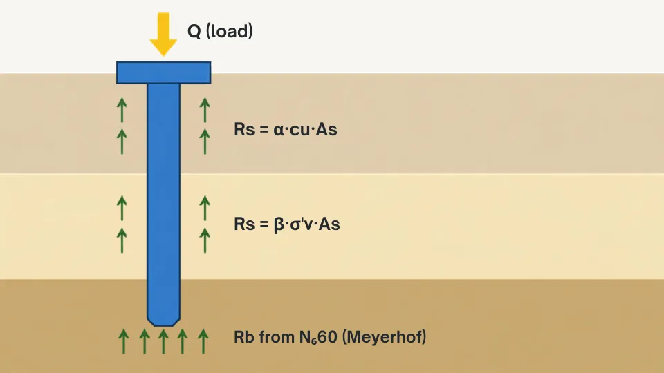
The ultimate geotechnical resistance of a single pile under compression is the sum of the base resistance and the shaft resistance:
where:
- is the base (end bearing) resistance, from the soil below the toe,
- is the shaft (skin friction) resistance, from the soil along the pile shaft.
The shaft mobilises first, at small displacements, and the base mobilises last, at displacements of the order of 10% of the pile diameter. A design that leans on the base must accept the displacement that the base needs, or verify it with a load test.
Shaft resistance in clay: the alpha method
In saturated clay, the undrained shear strength is the natural measure of the shaft friction. The alpha method is a total stress method:
where is the shaft area (perimeter embedded length) and is an adhesion factor that relates the peak unit shaft friction to . In soft clays is close to 1.0; in stiffer clays it drops, because the pile shaft does not mobilise the full undrained strength of the soil at the interface. Published guidance gives in two ways. Tomlinson’s adhesion curves relate directly to : for kPa they give to 0.90, so a design value of 0.80 is a conservative choice and the one used here. API RP 2GEO instead makes vary with depth through the ratio , with for , which in the profile of the worked example averages about 0.49. The sensitivity table at the end of the example shows what that difference is worth.
The alpha method is the right tool for undrained behaviour: the load goes in fast, the clay has no time to drain, and the resistance is governed by the undrained shear strength, not by effective stress.
Shaft resistance in sand: the beta method
Drained sand does not have a . Shaft friction there is frictional and grows with the effective stress holding the sand against the shaft:
where is the vertical effective stress at the depth being considered and is a coefficient that combines the lateral earth pressure coefficient and the interface friction angle :
For normally consolidated sand a common simplification (the “beta method” formula) is:
which for a medium-dense sand with gives . The unit shaft friction increases with depth (because increases), so the total shaft resistance is the integral of over the pile length in sand, which for a uniform profile collapses to the average effective stress times the shaft area.
Base resistance from SPT: Meyerhof’s correlation
The base resistance of a driven pile in sand is most often estimated from the SPT blow count. Meyerhof’s (1976) correlation is the one still taught and used:
where is the average SPT blow count in the bearing zone, is the embedment of the pile in the bearing stratum and is the pile width. Meyerhof’s original correlation used the uncorrected blow count; modern practice applies it with . The average is taken in the bearing zone, roughly 10 pile diameters above and 3 below the toe. The ratio is capped at 10: beyond ten diameters of embedment, the base resistance stops growing. The cap belongs to the correlation, not to a general critical-depth rule. For , the cap gives kPa.
That number deserves a warning. 10 MPa at the toe is the failure base pressure the correlation estimates; service pressures below it are fine, but a design that leans heavily on the base must demonstrate the settlement is acceptable, and a load test is the honest way to do it.
Which method when
| Situation | Method | Key parameter | Reference |
|---|---|---|---|
| Soft-to-firm clay, undrained | Alpha | , adhesion factor | Tomlinson; API RP 2GEO () |
| Sand and gravel, drained | Beta | , | Burland, 1973 (formulation); FHWA NHI-16-009 |
| Driven pile in sand, SPT available | Meyerhof SPT | , | Meyerhof, 1976 |
| Bored pile in clay | Alpha with reduced | Tomlinson; local codes | |
| Uplift | Shaft only | with reduced factors | EN 1997-1, 7.6.3 |
Worked example: driven pile in clay over sand
A column delivers a service load of 1,100 kN. Design one pile with a factor of safety of 2.5.
Input data
| Property | Value |
|---|---|
| Pile type | Driven precast reinforced concrete, square |
| Pile section | 450 mm × 450 mm |
| Embedded length | 18 m |
| Cross-section area | m² |
| Perimeter | m |
| Layer 1, 0–6 m | Soft clay: kPa, kN/m³ |
| Layer 2, 6–20 m | Medium-dense silty sand: , kN/m³, near the top of the layer rising to 30 at the toe (average 25 in the bearing zone) |
| Water table | 1.5 m below ground level |
| Adhesion factor (design) | 0.80 |
| Column service load | 1,100 kN |
| Required factor of safety | 2.5 |
Take kN/m³. Above the water table the clay is treated as moist with the same unit weight as saturated, so the effective unit weight above the table is 18.0 kN/m³ and below it is kN/m³. The sand effective unit weight is kN/m³.
Step 1: effective vertical stress profile
All stresses below are rounded to one decimal place; the arithmetic keeps full precision until the last step.
The water table sits at 1.5 m, so the clay above it carries no pore pressure:
Below the table, the clay adds effective stress at the submerged unit weight:
The sand layer, 12 m of it down to the toe at 18 m:
The average effective stress over the sand shaft (6 m to 18 m):
Step 2: shaft resistance in the clay
Using the alpha method over the 6 m of clay:
Step 3: shaft resistance in the sand
First the beta coefficient for (sin 32° = 0.530, tan 32° = 0.625):
Then the shaft resistance over the 12 m of sand:
Step 4: base resistance
The pile is embedded m in the bearing sand, so , which exceeds the cap of 10. The Meyerhof correlation caps the base pressure:
Step 5: ultimate and allowable capacity
Step 6: decision
The allowable capacity of 1,266 kN exceeds the column load of 1,100 kN, so the pile works geotechnically with an actual factor of safety of:
Two notes. First, the base contributes 2,025 of the 3,165 kN, 64% of the capacity, mobilised only after the displacement the base needs; the design should confirm the settlement and, on a real project, a maintained load test. Second, the structural check: at ULS the design load is kN, and the concrete alone with MPa for C30/37 ( per EN 1992-1-1) carries kN before any reinforcement, so the section is not the weak link here; drivability and handling stresses are.
How sensitive is the result to the adhesion factor?
The value is the least constrained input in this example, so it is worth testing how much it moves the answer:
| (design) | (kN) | (kN) | Actual |
|---|---|---|---|
| 0.50 | 216 | 3,035 | 2.76 |
| 0.60 | 259 | 3,078 | 2.80 |
| 0.80 (used) | 346 | 3,165 | 2.88 |
| API RP 2GEO | ~213 | ~3,032 | 2.76 |
The example survives the full range: even the API integration, the most conservative treatment, leaves a factor of safety of 2.76 against a required 2.5. The margin comes from the base, not from the clay shaft, which is why the load test matters: the correlation can be optimistic or pessimistic about the base, and only the test tells you which.
Group effects
Rarely is a column carried by one pile. The capacity of a pile group is not the number of piles times the single-pile capacity. Three mechanisms intervene:
- Efficiency. Piles close together shadow each other: the shaft resistances overlap, so each pile mobilises less than it would alone.
- Block failure. If the piles are close enough, the whole group fails as one large block, perimeter of the group times the shaft friction of the block plus the base of the block, which can be more or less than the sum of the piles depending on the spacing.
- Group settlement. A group settles more than one pile carrying the same average load. For a pile group in clay, the settlement is usually estimated as that of an equivalent raft at a depth of roughly two-thirds of the pile length.
Converse-Labarre efficiency
The simplest group efficiency estimate is the Converse-Labarre formula:
where and are the numbers of piles in the two directions and in degrees, with the pile width and the centre-to-centre spacing.
For a group of the 450 mm piles at a spacing of m:
The efficiency is 73%, so the group of 9 carries times the single-pile capacity, not 9 times. The alternative is the block check: whether the block governs depends on the geometry and the soil. In undrained clay the block tends to control at tight spacing (roughly 2 to 3 diameters); in loose sand the group can even gain capacity from densification. The block check is always worth running.
Negative skin friction and uplift
Two effects can make the shaft load work backwards:
- Negative skin friction. If the soil around the pile settles more than the pile (a fill placed over soft clay, a dropping water table), the shaft drags down on the pile instead of holding it up. This “dragdown” adds load to the pile and to the underlying bearing stratum. There is no universal formula; codes (EN 1997-1 clause 7.3.2) require estimating it from the settlement of the soil relative to the pile, and design practice counters it with a slip coating on the upper shaft, or by simply adding the drag force to the design load.
- Uplift. A pile in tension resists only with its shaft, , plus its own weight. Codes apply a partial factor to the shaft resistance in tension because shaft friction in tension is typically lower than in compression.
Checking the design: load tests
The calculation is an estimate, and the soil parameters it uses are estimates themselves. The load test is where the design meets the ground. Two families are standard:
- Static maintained load test. Load is applied in increments and held until the creep rate drops below the code limit. In the US the procedure follows ASTM D1143/D1143M; under the Eurocodes the test procedure is in EN 1997-1 clause 7.5 (7.5.2), and the measured resistance is turned into a characteristic value using the correlation factors of clause 7.6.2.2 (compression) and 7.6.3.2 (tension). The measured resistance is compared against the design value and the pile accepted or the design revised.
- Dynamic testing. A pile is re-struck with a hammer and instrumented (PDA), or analysed by wave equation during driving. Faster and cheaper than a static test, but it measures what happens under a dynamic event, and for that reason it is usually specified on a proportion of piles alongside static verification of one or two.
On a real project the number of tests is set by the code and the ground variability: more when the SPT blows scatter, fewer when the profile is uniform.
Common errors
- Summing shaft and base without considering displacement. The base of a driven pile needs roughly 10% of the pile width of movement to mobilise (bored piles can need more). If the structure cannot tolerate that, the base contribution should be discounted or the test schedule adjusted.
- Using on a drained problem. The alpha method needs undrained conditions. On a long-term, drained load (a high embankment next to the pile), drained parameters and an effective stress method are the ones that apply.
- Forgetting the water table. The beta method needs effective stresses, and the difference between 20 and 10 kN/m³ in the saturated case is the difference between a pile that works and one that does not.
- Averaging over the whole profile. The base correlation uses the blow count in the bearing zone near the toe, not from the top of the sand.
- Trusting the SPT cap blindly. 10 MPa at the toe is a failure estimate, not a service value; settlement and the load test, not the correlation, are what protect the structure.
- Treating the group as independent piles. At tight spacing, block failure and group settlement govern, and the Converse-Labarre or block check is not optional.
FAQ
What factor of safety should a pile have?
Common design practice is a factor of safety of 2.0 on piles verified by static load test and 2.5 to 3.0 when the capacity comes from calculation alone, like the example above. The US model codes set a minimum of 2.0. Codes do not fix a single figure across the board: EN 1997-1 works with partial factors and correlation factors instead of one global safety factor.
Which method should I use for a pile in clay?
The alpha method (total stress) for the short-term, undrained condition, which is the usual governing case for loading on a building foundation. For long-term drained loading, an effective stress method and parameters.
How deep must a pile penetrate the bearing layer?
There is no code figure for this: EN 1997-1 leaves it to calculation and the US model codes require only the penetration needed to develop the capacity. Published guidance varies: about 4 to 6 pile diameters as a common working rule (Tomlinson cites roughly 5 diameters), at least 8 diameters at the toe per USACE, and 10 diameters as the cap in the Meyerhof base correlation, beyond which the extra length adds shaft resistance instead. Treat the range as a sanity check, not a design rule.
Can I design a pile without a borehole?
No. Every capacity method in this article starts from soil parameters that come from the ground investigation. Designing from assumed parameters is a common shortcut, and it is the one that fails on site.
What is the difference between geotechnical and structural capacity?
Geotechnical capacity is what the soil can give back to the pile; structural capacity is what the pile cross-section can carry. The allowable pile load is the smaller of the two, which is why the pile length is set by the ground and the section by the load.
References
- EN 1997-1:2004+A1:2013, Eurocode 7: Geotechnical design — Part 1: General rules, clause 7.3.2 (negative skin friction), 7.5 (pile load tests, 7.5.2 static load tests) and 7.6 (axially loaded piles: 7.6.2 compressive ground resistance, 7.6.3 tensile ground resistance, 7.6.4 serviceability limit state).
- FHWA NHI-16-009, Design and Construction of Driven Pile Foundations, Volume I (FHWA GEC 12), Hannigan, P.J., Rausche, F., Likins, G.E., Robinson, B.R. and Becker, M.L., Federal Highway Administration, 2016. https://www.fhwa.dot.gov/engineering/geotech/pubs/gec12/nhi16009_v1.pdf
- ASTM D1143/D1143M, Standard Test Methods for Deep Foundation Elements under Static Axial Compressive Load, ASTM International.
- Meyerhof, G.G. (1976), Bearing capacity and settlement of pile foundations, ASCE Journal of the Geotechnical Engineering Division, 102(GT3), 195-228.
- API RP 2GEO (2011, 2nd edition 2024), Geotechnical and Foundation Design Considerations, American Petroleum Institute (the depth-dependent formulation).
- Tomlinson, M.J. & Woodward, J. (2014), Pile Design and Construction Practice, 6th edition, CRC Press.
- Burland, J.B. (1973), Shaft friction of piles in clay: a simple fundamental approach, Ground Engineering, 6(3), 30-42 (the formulation for shaft friction in clay, later extended to drained soils).
- USACE EM 1110-2-2906, Design of Pile Foundations, US Army Corps of Engineers.