

retaining wallsfoundations
Shoring Design: Excavation Support with a Worked Example
How shoring design works: apparent earth pressure for braced cuts, strut and wale loads, sheet pile sizing, and a 6 m excavation worked step by step.

A two-level basement, a pipe trench beside a live road, a lift pit inside a building that has to stay open. Each one is a hole in the ground with vertical sides, and each one needs a structure that holds the ground back while it is open. That structure is the shoring.
Shoring design is not the same exercise as designing a permanent retaining wall. The wall is on site for a few months, it is built in stages, and on most urban sites what governs the result is not the wall’s own factor of safety but how far the ground behind it moves. This guide covers how the loads are estimated for a braced cut, how those loads turn into strut, wale and sheet pile sizes, and what else has to be checked before any of those numbers mean anything. It closes with a 6 m excavation worked through step by step.
What shoring is, and how it differs from a retaining wall
Shoring, or support of excavation, holds back soil, water and the structures next to a cut while the permanent works are built. Two subsystems are designed separately and then checked together:
- the earth retention system, which is the wall in contact with the soil: steel sheet piles, soldier piles with lagging, secant or contiguous pile walls, diaphragm walls;
- the support system, which stops the wall from moving: struts, rakers or cross-bracing inside the cut, or tiebacks and ground anchors drilled into the ground behind it.
Three things separate this from the permanent wall in the step-by-step retaining wall design guide:
- It is temporary. Design life is weeks or months, the load cases are construction stages rather than the finished structure, and steel sections are usually extracted at the end and reused.
- It is built in stages. The excavation advances in steps and each prop is installed at its level before the next step is dug. The wall is loaded and supported progressively, not once.
- Ground movement is the criterion, not just stability. Next to a road, a masonry building or a gas main, the design target is often a movement limit of a few millimetres, and the wall can be perfectly stable while the building above it cracks.
The types of shoring, and what decides between them
In practice the choice comes down to six systems:
- Cantilever sheet piles. The simplest and cheapest wall: driven sheets with no props, working through their own bending stiffness. Practical to roughly 3 m (10 ft) of retained height in decent ground, because the bending moment grows with the square of the height and the section size follows.
- Braced or anchored sheet piles. The same wall with struts across the cut or tiebacks behind it. This is the standard solution for deeper basement and infrastructure excavations.
- Soldier piles and lagging. Steel H piles driven or drilled at 1.5 to 2.5 m centres with timber or concrete lagging between them as the cut is dug. Quick, economical, and best kept above the water table, because there is no cut-off.
- Secant and contiguous pile walls. Overlapping or touching bored piles. Stiff, quiet, and the natural choice when the wall must also cut off groundwater.
- Diaphragm walls. Concrete cast in a panel trench. The heavy solution, used when the excavation is deep enough that the wall becomes part of the permanent structure.
- Soil nailing. Reinforcement installed into the soil in stages as the cut goes down. It works in ground that can stand unsupported for a day or two at a time, and it is not a solution below the water table or in soft clays.
What picks between them: the depth of the cut, whether the excavation goes below the water table, how wide the cut is (struts need something to push against on the other side; tiebacks need space and a neighbour’s consent for the anchor), the soil, noise and vibration limits, and whether the wall is staying in as part of the finished works.
For utility trenches the whole question is usually about protection rather than structural engineering. Any excavation 1.5 m (5 ft) or deeper needs a protective system under 29 CFR 1926.652(a)(1), and a trench box, shield or hydraulic shoring from a manufacturer’s tabulated data is what a competent person will normally call for.
Why the Rankine triangle is the wrong load for a braced cut
The classical earth pressure theories assume the wall yields far enough for the soil behind it to reach the active state. A braced cut never gets that far. The top strut goes in almost immediately, and below the excavation level the wall is held by passive resistance, so the pressure distribution measured in the field looks nothing like a triangle: it is close to uniform with depth, and it is larger than the active value in the upper part of the wall (Peck, 1969).
Designing a deep braced cut on a Rankine triangle therefore underestimates the load on the upper struts. The standard practice is to design struts against an apparent earth pressure diagram, an empirical envelope derived from measurements in braced cuts, and to keep the classical theories for walls that are free to yield.
For a uniform dry sand the envelope is a rectangle (Peck, 1969):
where is the excavation depth, the unit weight of the sand and its effective friction angle. The diagram is valid when the water table sits below the bottom of the cut, which is the case the whole method assumes.
For clays, Peck gives two envelopes, separated by the stability number :
- Stiff fissured clay (): the pressure varies with depth between and , and is taken as a lower limit unless measurements on comparable cuts in the same deposit justify less.
- Soft to medium clay (): the envelope is a trapezoid with
with the average undrained shear strength over the depth of the cut.
Two additions are always separate from the envelope. A uniform surcharge on the retained side, from a road, a spoil heap or a crane, adds to the pressure. Water below the water table adds full hydrostatic pressure and removes the validity of the sand diagram, which is why dewatering or a cut-off wall is a design decision and not a site convenience.
From pressure to strut, wale and wall sizes
The envelope gives a pressure, and the pressure still has to be turned into a strut load and a steel section. The method that hand calculations and software both follow is a vertical beam model (Peck, 1969):
- Draw the envelope over the full depth of the cut and mark the strut levels on it.
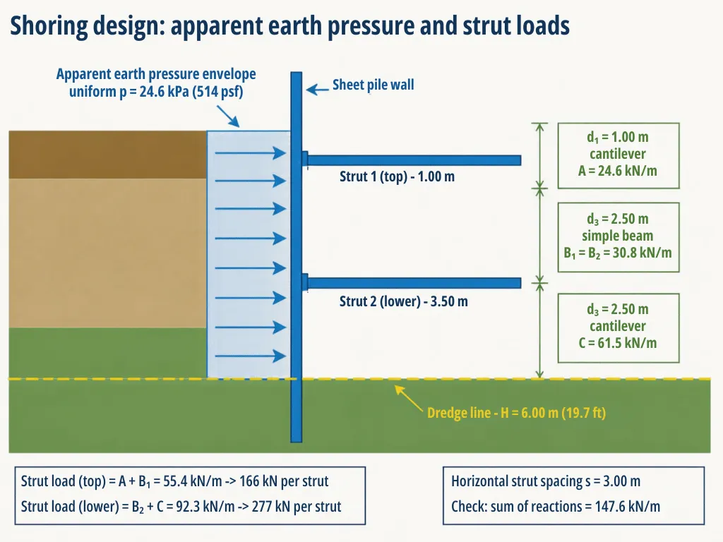
- Cut the envelope into spans. The wall is treated as a cantilever above the top strut, a simply supported beam between each pair of struts, and a cantilever again below the lowest strut. Hinging the wall at every strut except the top is an acceptable and common simplification.
- Take the reactions. Each span reaction is a force per metre of wall; the load on a strut is the reaction at its level multiplied by the horizontal strut spacing.
- Bend the members. The wall takes the largest of the span moments. The wale, the horizontal beam that distributes the wall pressure into the struts, takes the strut reactions as a beam of span equal to the strut spacing.
The section modulus then follows from the moment and an allowable stress. In the allowable stress method it is ; under Eurocode 3 the check on a steel sheet pile is (EN 1993-5), with the geotechnical side of the wall designed to EN 1997-1.
Worked example: a 6 m excavation in sand
A basement excavation 6.00 m (19.7 ft) deep in medium-dense sand, with a road and a plant access route along one edge. Two strut levels, at 1.00 m and 3.50 m below the top of the cut, at 3.00 m horizontal spacing. The water table is 2 m below the base.
| Input | Value |
|---|---|
| Excavation depth | 6.00 m (19.7 ft) |
| Unit weight of sand | 18.0 kN/m³ (114.6 pcf) |
| Effective friction angle | 32° |
| Surcharge on the retained side | 10 kPa (209 psf) |
| Strut levels below the top | 1.00 m and 3.50 m (3.3 ft and 11.5 ft) |
| Horizontal strut spacing | 3.00 m (9.8 ft) |
| Steel sheet pile grade | S 270 GP, = 270 MPa |
Step 1: active earth pressure coefficient.
Step 2: apparent earth pressure, plus the surcharge.
The pressure is uniform over the full depth, which is what makes this envelope so easy to work with.
Step 3: total horizontal force on the wall.
That single number is a useful check on everything that follows: the sum of the strut reactions per metre of wall must come back to it.
Step 4: strut loads. The envelope is split into a 1.00 m cantilever above the first strut, a 2.50 m simply supported span between the struts, and a 2.50 m cantilever below the second strut. Taking reactions per metre of wall:
The strut at the upper level takes kN/m of wall; the lower strut takes kN/m. The four reactions add up to 147.7 kN/m against the 147.6 kN/m total from Step 3, the difference being the one-decimal rounding of the reactions. Multiplying by the 3.00 m strut spacing:
| Strut level | Reaction per m of wall | Design strut load |
|---|---|---|
| Upper (1.00 m) | 55.4 kN/m | 166 kN (37 kip) |
| Lower (3.50 m) | 92.3 kN/m | 277 kN (62 kip) |
Peck’s own note is worth keeping in mind here: the most probable load in an individual strut is about 25 percent below the maximum, because the struts do not all engage at once. The design still uses the envelope value, and if anything is jacked, the preload is set from it.
Step 5: wall bending moment and section. The largest span moment governs. For a cantilever of length , ; for the simply supported span, :
The bottom span governs. The required elastic section modulus per metre of wall is:
Any standard sheet pile section above that value works in bending, and lighter Z sections sit well above it. What usually decides the section in the end is not this number: it is driveability, the stiffness needed to hold the movement limit, and the corrosion allowance if the wall stays in the ground.
Step 6: the wales. The wale at the lower level picks up 92.3 kN/m of wall and spans 3.00 m between struts. Treated as simply supported:
a normal rolled steel section. Corners, splices and the connection between wale and strut are the parts that actually get built badly, and they deserve as much attention as the bending check.
Step 7: what this calculation has not done. It has sized the wall, the struts and the wales against the horizontal load. It has not checked the ground: the toe below the dredge line, the stability of the base, seepage, or how much the road behind the wall will settle. Those checks are what tell you whether the excavation can be built as drawn.
The checks outside the wall
Toe embedment and passive resistance. Everything above assumes the wall is held at the dredge line, and what holds it there is passive resistance in the ground below the excavation level. That resistance is mobilised only after the soil has moved, so designs do not use the full theoretical : the classical approach applies a factor of about 2, and EC7 handles the same conservatism with a partial factor on the passive resistance. Practical minimums are compiled in the NCSEA Excavation Shoring Design Guide, which sets a toe depth of not less than 1.8 m (6 ft) for restrained walls under 6 m (20 ft) high and 2.4 m (8 ft) above that (STRUCTURE, 2022).
Base heave. In soft clay, the base of the cut can fail as a bearing capacity problem: the clay below the excavation is pushed up by the weight of the ground on either side. Terzaghi’s check (Terzaghi, 1943) is
for a cut of width in clay of uniform strength, with a hard layer deeper than below the base, and being Terzaghi’s bearing capacity factor for a strip at . Where a hard stratum is met at a shallower depth , is replaced by . Let the soft clay run deeper than that and the expression tends to , and the factor of safety of 1.5 that is normally required cannot be reached. Numbers make the point: a 12 m wide, 6 m deep cut with = 25 kPa and = 18 kN/m³ gives
which passes, but only just, and that value already assumes the failure surface can develop the full 0.7B below the base. With the same clay extending deep below the cut, and the base is not stable at that depth without ground improvement or a longer wall.
Seepage and piping. Once the excavation is below the water table, water flows towards it and the effective stress at the base drops. If the upward seepage gradient reaches the critical gradient , the soil boils and the base loses all strength. Checks are done on the exit gradient, with factors of safety of the order of 2, and they set how much dewatering or how deep a cut-off is needed.
Movement of the neighbours. Field measurements compiled by Clough and O’Rourke (1990) put maximum lateral wall movements at around 0.2 percent of the excavation depth for well-built braced cuts in stiff clays and granular soils, and well above 1 percent where the ground is soft or the workmanship is poor. Those movements propagate: settlement behind the wall is typically a similar fraction of the excavation depth, and whether it matters is a question about the building, not about the soil. The standard method is Boscardin and Cording (1989), which relates angular distortion and horizontal strain to damage categories, and it is the framework behind most movement limits set in shoring specifications.
Water changes the whole calculation
Everything in the worked example rests on the water table being below the base. Put water in the picture and three things change at once:
- The pressure is no longer soil alone. Hydrostatic pressure is added to the earth pressure, and because it acts over the full depth it is usually the larger term below the water table.
- The sand envelope is no longer valid. It was derived from cuts with the water table below the dredge line, and applying it below the water table is a mistake that shows up as a heave or a boil.
- The base has to be protected. Either the water is pumped out, with wellpoints, deep wells or ejectors, and the excavation is designed drained; or the wall cuts the water off, secant piles or diaphragm walls reaching an impermeable layer, and the base is designed for hydrostatic uplift. The first option moves the problem to the neighbours (their ground settles when you pump it), and the second costs more but keeps the water where it is.
Sequence, preload and monitoring
The design numbers only survive contact with the site if the sequence is right. Struts go in before the excavation passes their level, never after; the wall deflects most in the stage when a prop has not yet been installed, and no amount of later jacking puts the ground back. The classical practice for strut spacing is a minimum vertical spacing of about 2.75 m (9 ft), with bracing or splices at intermediate points to keep the struts from buckling over the width of the cut.
Struts and anchors are preloaded, jacked against each other or stressed to a set proportion of the design load, so that they are engaged from the moment the ground starts to move. It is a small step in the programme and it is what makes a strut replace an unplanned for excavation of a few centimetres of ground.
Then the design is verified as it is built. Inclinometer tubes in or behind the wall, settlement and movement points on adjacent buildings and services, and piezometers where pumping is running, with trigger and action levels agreed in advance. Where the site is sensitive, the observational method is the honest approach: design for a range of conditions, measure, and adjust the props, the pumping or the excavation sequence as the readings come in.
Six ways a shoring design fails
- The Rankine triangle used on a braced cut. The upper struts are under-designed, and they are the ones that must hold when the wall is least supported.
- No surcharge in the envelope. A road, a spoil heap or a crane beside the cut is a load on the wall, and it is the load that most often gets left out.
- Water ignored. The design assumes a dry cut; the site has a water table at half the excavation depth, and the pressure has doubled.
- Toe too short. The wall is designed for bending and the passive resistance at the toe is never checked, so the wall rotates and the ground behind it drops.
- No preload, or struts installed behind the excavation. The wall has already moved before the loads arrive, and the movement shows up in the building next door.
- No monitoring on a sensitive site. Movement was never measured, so nobody knew it was happening until the cracking started.
Frequently asked questions
What is the difference between shoring and a retaining wall? A retaining wall is a permanent structure, designed for the finished ground profile and the structure behind it. Shoring is a temporary structure that holds a construction excavation open, designed for construction stages and for movement limits on the neighbours, and generally removed at the end of the job. The same theories of earth pressure sit behind both, but the load cases and the governing criterion are different.
How deep can a cantilever sheet pile go? As a rule of thumb, up to about 3 m (10 ft) of retained height in good ground. The bending moment on a cantilever grows with the square of the height while the passive resistance at the toe has to grow with it, so the section gets heavy quickly. Beyond that depth, a single row of struts or tiebacks is normally cheaper than the extra steel.
How do you calculate strut loads? From the apparent earth pressure diagram. Divide the envelope into spans between the strut levels, take the reactions of those spans per metre of wall, and multiply by the horizontal strut spacing. Add the two reactions that meet at each strut level. That gives the design load, which is what the strut section, the wale and the connection are sized against.
Do I need a designed shoring system for a 2 m trench? In the United States, any employee in an excavation 1.5 m (5 ft) or deeper must be protected from cave-ins under 29 CFR 1926.652(a)(1). That can be met with sloping, with a manufacturer’s tabulated trench box or shield, or with a system designed by a registered engineer. The choice belongs to a competent person, and the trigger is the depth, not the soil.
What factor of safety is used against base heave? 1.5 against the Terzaghi mechanism, with the clay strength taken as the average over the depth that the failure surface can reach. Where the soft clay extends deep below the excavation, the check can show that the required factor of safety is unreachable at the planned depth, and the answer is to reduce the depth, improve the ground, or drive the wall deeper so it adds resistance below the base.
When is a tieback better than a strut? Tiebacks keep the inside of the excavation clear, which matters when the cut is wide, when the plant needs to work in it, or when the permanent structure would clash with the bracing. They need ground behind the wall that can hold an anchor and, in most places, a written agreement with the neighbouring owner. Struts need the opposite: a cut narrow enough to bridge, and a design that accepts the obstruction.
Where to go next
If the wall is permanent, the design changes: start with the retaining wall design guide, which works the free-earth pressures that a permanent wall is designed on. The pressure the shoring carries comes from the investigation, and reading a geotechnical report is where the shell and the friction angle and the water table are actually found.
If the ground below the excavation is the problem, the options are in ground improvement techniques and soil stabilization. If the shoring has to hold up an existing building rather than empty ground, that is a different set of checks, covered in underpinning methods.
You can size the retained earth and the base pressures behind the wall with the retaining wall tools, and check what the ground below the excavation is doing at the same time with the deep foundation tools.
References
- Peck, R. B. (1969). “Deep Excavations and Tunneling in Soft Ground”. Proceedings of the 7th International Conference on Soil Mechanics and Foundation Engineering, Mexico City, State-of-the-Art Volume, 225-290.
- Terzaghi, K. (1943). Theoretical Soil Mechanics. Wiley. (Stability of the bottom of a braced cut in clay.)
- Terzaghi, K., & Peck, R. B. (1967). Soil Mechanics in Engineering Practice, 2nd ed., Wiley. (Apparent earth pressure diagrams for braced cuts.)
- Sitharam, T. G. Advanced Foundation Engineering — Chapter 6: Braced Cuts. NPTEL / Indian Institute of Science, Bangalore. PDF (worked statement of the Peck envelopes, strut, wale and sheet pile design steps used here.)
- CEN (2004). EN 1997-1: Eurocode 7 — Geotechnical design — Part 1: General rules. (Design of earth-retaining structures and the treatment of passive resistance with partial factors.)
- CEN (2007). EN 1993-5: Eurocode 3 — Design of steel structures — Part 5: Piling. (Bending resistance of steel sheet piles.)
- ArcelorMittal Sheet Piling. Design of steel sheet piles. Link (EN 1993-5 checks, elastic and plastic section moduli, driveability.)
- FHWA (1999). Ground Anchors and Anchored Systems, Geotechnical Engineering Circular No. 4, FHWA-IF-99-015. PDF
- OSHA. 29 CFR 1926.652 — Requirements for protective systems. Link
- Cortnik, B. G. (2022). “Excavation Shoring Design Guide”. STRUCTURE Magazine, November 2022. Link (summary of the NCSEA guide and its minimum toe depths.)
- Clough, G. W., & O’Rourke, T. D. (1990). “Construction-Induced Movements of In-Situ Walls”. Design and Performance of Earth Retaining Structures, ASCE Geotechnical Special Publication No. 25, 439-470.
- Boscardin, M. D., & Cording, E. J. (1989). “Building Response to Excavation-Induced Settlement”. Journal of Geotechnical Engineering, ASCE, 115(1), 1-21.