
User Manual
This section provides a detailed description of each feature of the program. It explains how to create, edit, view, and analyze an open channel model, as well as how to use the different tools available in the interface.
The purpose of this manual is to serve as a reference for understanding the complete functionality of the software, from the initial project configuration to the interpretation of the results. You can consult it at any time to resolve specific questions about the use of a feature or workflow.
Input parameters
Section titled “Input parameters”Type of analysis
Section titled “Type of analysis”The types of analysis allow you to add new calculations when running the model.
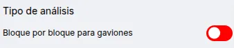
The following types of analysis are currently available:
- Block by block for gabions: This analysis will calculate the stability for overturning and sliding for each block in a modular structure such as gabion walls.
Foundation soil
Section titled “Foundation soil”The foundation soil is used to calculate the bearing capacity and passive earth pressure of the soil. It supports one (1) type of soil.
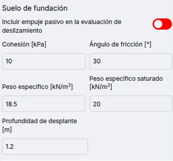
The available parameters for the foundation soil are:
- Include passive thrust in the sliding safety factor assessment: Calculate and include passive pressure in the sliding safety factor. It is not included overturning or bearing capacity.
- Cohesion
- Friction angle
- Unit weight
- Saturated unit weight
- Embedment depth
Backfill
Section titled “Backfill”The fill is used to calculate the active earth pressure acting on the structure. It supports multiple layers of soil.
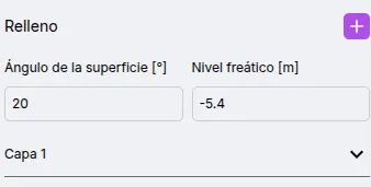
The available parameters for wall backfill are:
- Surface Angle: The angle of the fill surface, which affects the direction of the active pressure vector.
- Water table level
- Soil Layers
Add and edit soil layers
Section titled “Add and edit soil layers”The fill supports multiple layers of soil.
To add a new soil layer, click on the button.

Once you click the button, a new soil layer will appear in the list.
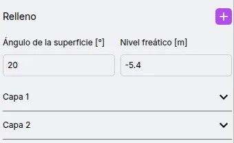
To edit the parameters of a layer, click on it in the list. You can now view and edit the available parameters.
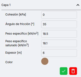
After editing, press the ** ** button.

To remove a soil layer, press the ** ** button.

The available parameters for soil layers are:
- Cohesion
- Friction angle
- Unit weight
- Saturated unit weight
- Thickness
Structure
Section titled “Structure”The wall structure is made up of stacked elements.
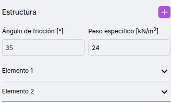
The available parameters for the structure are:
- Friction angle: Only for the evaluation of slippage in gabions. Used to calculate base friction.
- Unit weight: Corresponding to the structural material.
Add and modify structural elements
Section titled “Add and modify structural elements”To add a new structural element, click on the button.

Once you click the button, a new structural element will appear in the list.
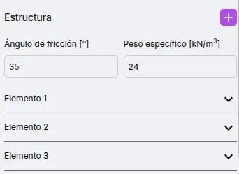
To edit the parameters of a structural element, click on the element in the list. You can now view and edit the available parameters.
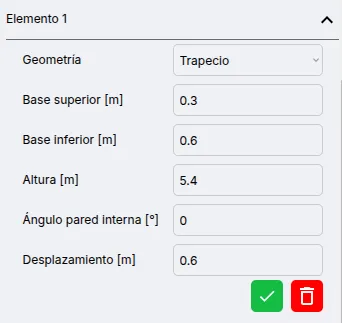
After editing, press the ** ** button.
To delete a structural element, click the ** ** button.
The available parameters for the structural elements are:
- Geometry: Allows you to select between rectangle and trapezoid.
- Upper base: Only for trapezoid.
- Lower base: Only for trapezoid.
- Height
- Internal wall angle: For trapezoid only. Measured from the vertical, counterclockwise.
- Offset: Moves the element horizontally.
Results
Section titled “Results”Geometry
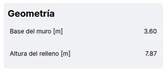
Section titled “Geometry”It contains the main values that define the shape of the wall:
- Base of the wall (B)
- Fill height (H’): When the fill surface angle is 0°, this value corresponds to the height of the structure. However, if the angle is greater than 0°, also consider the segment of the ground above the wall up to the outer edge of the structure.
Lateral earth pressure
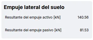
Section titled “Lateral earth pressure”It shows the pressures acting on the wall:
- Active pressure: Corresponds to the active pressure vector, whose direction follows the slope of the fill surface. It is broken down into horizontal and vertical components for analysis. It also includes hydrostatic pressure if the fill is saturated.
- Passive thrust: Corresponds to the passive pressure vector, including hydrostatic pressure.
Calculation of force and moments
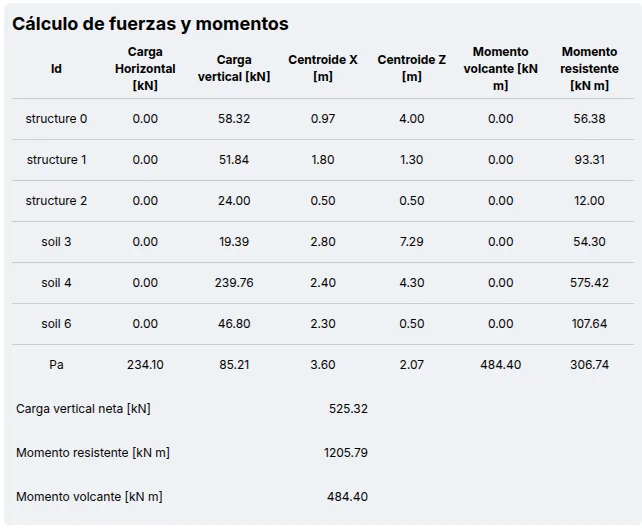
Section titled “Calculation of force and moments”It presents the calculation of forces and moments for each element that makes up the wall, including the ground considered part of the structure. It then provides a summary of net vertical load, resisting moment, and overturning moment.
Overturning assessment
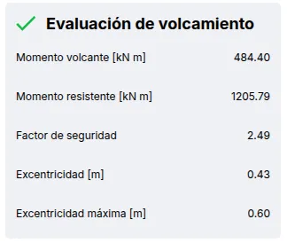
Section titled “Overturning assessment”Based on the previous results, the safety factor and the eccentricity of the load are calculated. The safety factor is compared to a value of 2.0.
Sliding assessment
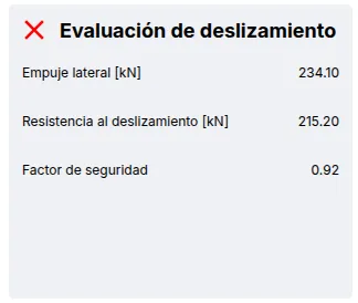
Section titled “Sliding assessment”Based on the previous results, the safety factor is calculated and compared to 1.5.
Assessment of load-bearing capacity
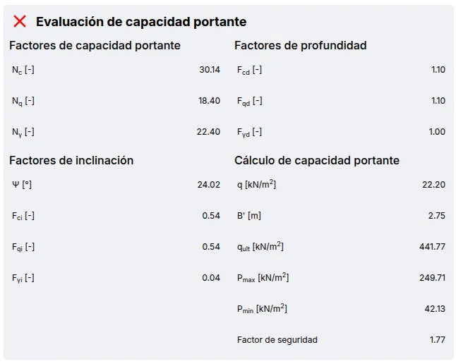
Section titled “Assessment of load-bearing capacity”Based on the previous results, the safety factor is calculated and compared to 3.0.
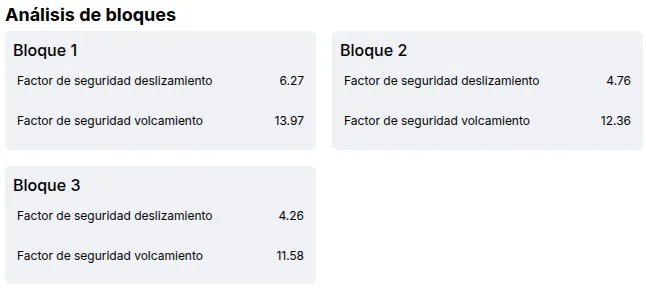
Block-by-block analysis
Section titled “Block-by-block analysis”It presents the results of the block-by-block analysis.