Calculate your retaining walls with Rischio.io completely free
Are you looking for software to calculate retaining walls? With Rischio.io you can calculate any type of retaining wall quickly and easily. Our platform is 100% cloud-based, so you can work from anywhere and on any device. Sign up now completely free and discover a new way to create.
Try our platform now! Sign up for free
Conventions of a retaining wall
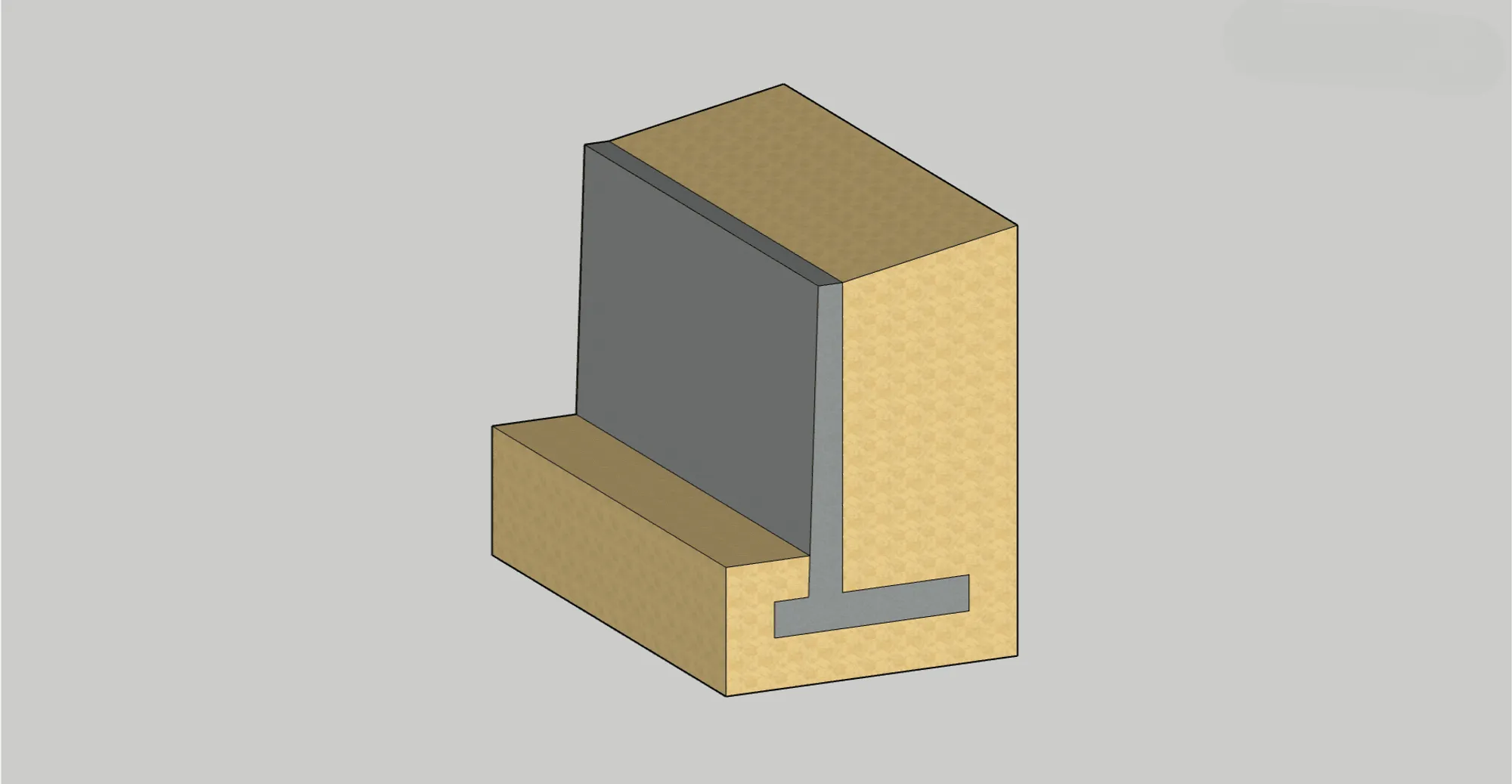
A retaining wall consists of multiple elements or parts, which are shown in the diagram below.

These elements are:
- Stem or wall: This is the main structural element of the retaining wall, responsible for resisting the pressure from the retained soil. It can be made of reinforced concrete, masonry, or other structural materials.
- Back face: This is the part of the wall that is in contact with the retained soil and bears the lateral earth pressure.
- Front face: This is the exposed part of the wall, generally visible and without direct contact with the fill.
- Counterfort: These are vertical elements located on the front face of the wall and perpendicular to it. Their function is to reinforce the structure, increasing rigidity and reducing bending moments at the base.
- Footing: This is the base of the retaining wall, responsible for distributing loads to the foundation soil to ensure structural stability.
- Toe: This is the front part of the footing that extends toward the front face of the wall. It helps improve stability against overturning.
- Key: This is an element that protrudes from the bottom of the footing, usually located at the base of the wall. Its main function is to increase resistance to sliding by generating passive earth pressure.
- Heel: This is the rear part of the footing that extends into the retained soil, providing additional stability to the wall.
- Backfill: This is the granular material or soil placed behind the retaining wall, over the heel. Its purpose is to reduce lateral pressures and facilitate water drainage.
What is analyzed when designing a retaining wall?

When designing a retaining wall, three possible failure mechanisms must be analyzed:
- Overturning failure: when the acting moments exceed the resisting moments.
- Sliding failure: when the acting horizontal forces exceed the resisting horizontal forces.
- Bearing capacity failure: when the vertical forces exceed the bearing capacity of the soil.
Step-by-step guide
Having understood the elements that make up a retaining wall and the failure mechanisms we need to consider, we present the step-by-step process for designing your retaining walls.
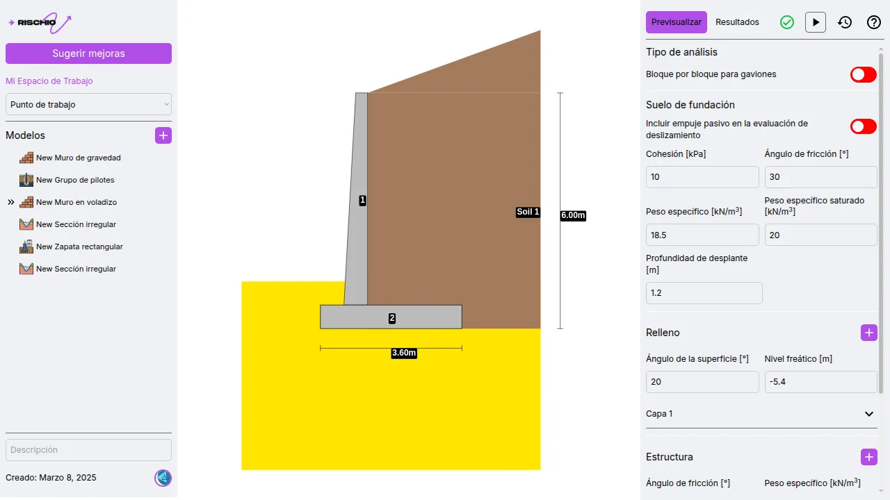
1. Calculation of acting forces on the wall

The acting forces on a retaining wall correspond to:
- The weight of the structure itself.
- The weight of the soil on the heel, including the upper wedge when the backfill is sloped.
- The active pressure of the backfill.
- The passive pressure of the soil corresponding to the foundation depth on the front face (optional).
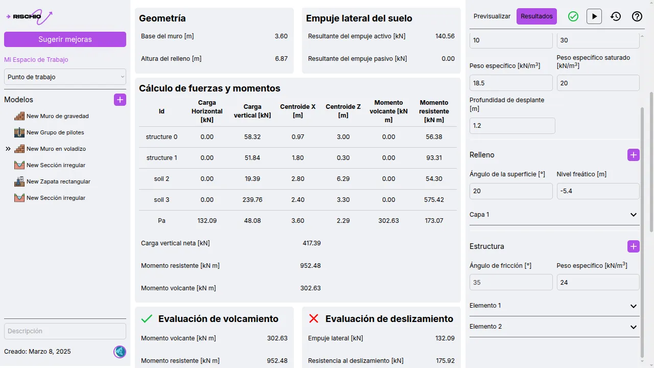
2. Safety factor for overturning
To calculate the safety factor for overturning, it is necessary to calculate the acting moments on the wall with respect to the base of the toe.
These moments should be classified into two groups:
- Overturning moments: these are the moments that destabilize the structure, generally the horizontal component of the active pressure.
- Resisting moments: these are the moments that stabilize the structure, generally the weight of the structure itself and the weight of the soil on the heel.
Note that the equations presented correspond to the case proposed in this article and should be adapted according to the conditions of your projects, which may include multiple types of soil in the backfill, a different type of wall, among others.
Once the overturning moments and resisting moments have been calculated, the safety factor for failure due to overturning should be calculated.
Usually, this safety factor is expected to be greater than 2.0; however, this value may vary depending on regulations and project requirements.
Also, it should be verified that the eccentricity of the applied loads is less than to avoid stresses at the base of the wall, which would create unsafe conditions for the wall.
Where corresponds to the sum of the vertical forces, which usually include the weight of the structure, the weight of the soil on the heel, and the vertical component of the active pressure.
3. Safety factor for sliding
The calculation of the safety factor for sliding requires calculating the destabilizing horizontal forces and the stabilizing horizontal forces.
- Destabilizing forces: This generally includes the active pressure of the soil and the hydrostatic pressure, depending on the wall’s condition.
- Stabilizing forces: This corresponds to the resistance at the base of the wall and the passive pressure of the soil on the front face (optional).
Where:
- corresponds to the friction angle between the wall and the soil. It is commonly used that
- corresponds to the adhesion between the wall and the soil. It is commonly used that
With these variables, the safety factor for sliding is calculated.
Typically, this safety factor is expected to be greater than 1.5; however, this value may vary depending on regulations and project requirements.
4. Safety factor for bearing capacity
Finally, to calculate the safety factor for bearing capacity, we need to calculate the maximum vertical pressure applied to the soil and its bearing capacity.
- Maximum vertical pressure: Since it is an eccentric load, the pressure distribution on the soil will not be uniform. The maximum pressure is defined as:

An additional verification is that pressures must always be positive, meaning no tension should be generated in the soil.
- Bearing capacity: In this case, the retaining wall is modeled as a continuous footing, and its bearing capacity is calculated using the General Bearing Capacity Equation or Meyerhof’s equation.
Where:
- , , are the bearing capacity factors of Meyerhof’s equation.
- . This value can be affected by the water table level at the front face of the wall.
- . In some cases, the eccentricity may be negative, so it is recommended to take its absolute value for this calculation.
- Depth factors
- Inclination factors
The shape factors (, , and ) are not included in this equation since, being a continuous footing, these tend to zero.
Attention should be paid when selecting the soil parameters corresponding to cohesion, friction angle, and unit weight, as these are for the foundation soil and not the backfill.
Once the bearing capacity and maximum pressure are calculated, the safety factor should be computed.
Typically, this safety factor is expected to be greater than 3.0; however, this value may vary depending on regulations and project requirements.
Recommendations if any of the safety factors are not met
There will be situations where the retaining walls do not meet some of the safety factors or conditions mentioned earlier, in which case our design must be reevaluated. It is important to understand the reasons why these factors are not met in order to make decisions that optimize the use of resources in the projects.
Some recommendations to improve the stability of retaining walls are:
- Increase the base of the wall: increases the resisting moments, the resistance at the base, and the bearing capacity.
- Reduce the height of the wall: decreases the active thrust.
- Change the fill material to a lighter one: reduces the active thrust.
- Change the type of wall: the geometry especially influences the resisting moments.
- Control the water table of the fill: proper management of water on the rear face of the wall should always be done, so it is important to have a good drainage system to prevent water accumulation.
Example calculation
Calculate the factors of safety for overturning, sliding, and bearing capacity for the retaining wall in the following figure.
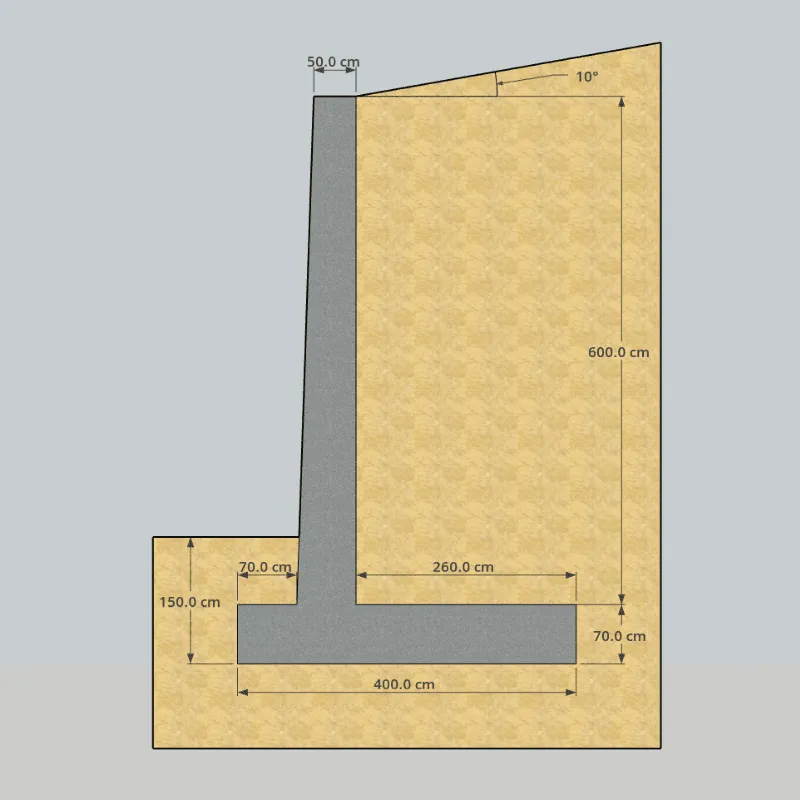
1. Identify the elements that make up the wall and the forces it is subjected to
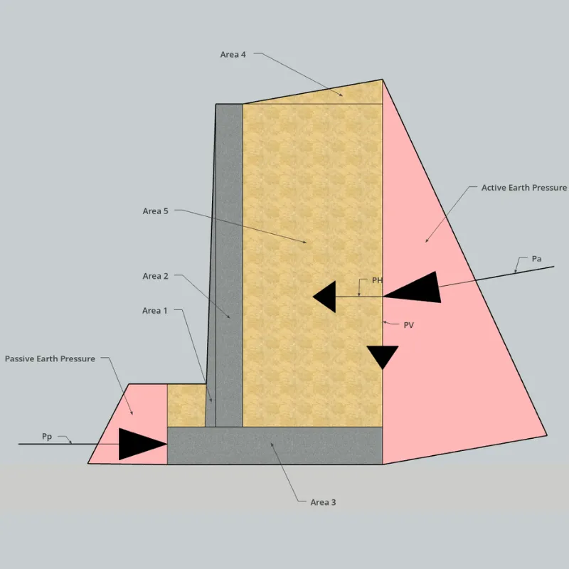
In this case, the structure is divided into figures 1, 2, and 3. The soil on the heel corresponds to figures 4 and 5. Lastly, the active thrust () is identified along with its horizontal component () and vertical component ().
Additionally, the value of H’ is calculated.
2. Calculate active and passive thrust
First, we need to calculate the active thrust coefficient of the fill.
The active thrust is calculated quickly as it is a triangular area.
Next, we calculate the passive thrust coefficient.
On the other hand, the passive thrust is a trapezoid, which we define as follows.
Now, we calculate the area of the trapezoid to obtain the passive thrust.
3. Calculate the forces and moments applied to the wall
Once the forces are obtained, we need to calculate the weight of each element, its centroid relative to the toe, and with this, we will find the sum of the vertical forces (), and the overturning moments () and resisting moments ().
| Element | Area | Vertical Force-Weight | Horizontal Force | ||||
|---|---|---|---|---|---|---|---|
| 1 | 2.5 | 60 | * | 1.16 | * | 69.6 | * |
| 2 | 5.0 | 120 | * | 2 | * | 240 | * |
| 3 | 3.0 | 72 | * | 1.5 | * | 108 | * |
| 4 | 0.045 | 0.81 | * | 2.83 | * | 2.29 | * |
| 5 | 2.5 | 45 | * | 2.75 | * | 123.75 | * |
| * | * | 109.46 | * | 2.03 | * | 222.2 | |
| * | 19.30 | * | 3 | * | 57.9 | * | |
With these results, the path to calculate the factor of safety for overturning and sliding is cleared.
4. Calculate the factor of safety for overturning and the eccentricity
Following the formula presented earlier, we calculate the factor of safety.
The safety factor requirement is met.
On the other hand, the eccentricity check.
The eccentricity requirement is met.
5. Calculate the factor of safety for sliding
Applying the equation presented.
The safety factor requirement is met.
6. Calculate the factor of safety for bearing capacity
We have reached the final verification, for which we will also use the values calculated in step 3.
We begin by calculating the maximum pressure on the soil.
Now, we verify that the minimum pressure is positive to avoid soil tension.
The verification is correct.
Now, we have the denominator for the safety factor, and we just need to calculate the bearing capacity.
We start with the bearing capacity factors from the Meyerhof Equation.
Next, we calculate the overburden pressure and the effective width of the footing.
Then, we use the depth factors.
Lastly, we calculate the inclination factors.
With these values, we can now calculate the soil bearing capacity.
Finally, we calculate the safety factor.
In this case, the safety factor requirement is not met, so it is necessary to redesign it according to the guidelines in this guide and recalculate. A good starting point could be increasing the base width of the wall.
References
- Das, B. M., & Sivakugan, N. (2018). Principles of Foundation Engineering.