

Lateral earth pressure is the horizontal stress a soil puts on a structure that holds it back: a retaining wall, a basement wall, a sheet pile, a bridge abutment. On a retaining wall it is the main load that tries to slide and overturn the wall. On the shaft of a pile in sand, the same horizontal stress is what gives the shaft its friction.
How large it is depends above all on how the wall moves. This guide covers the coefficient of lateral earth pressure, the three states (at rest, active and passive), how a pressure diagram becomes a force, and a worked example with two soils, a water table and a tension crack. The free lateral earth pressure calculator gives the coefficients and thrusts for a single backfill in the browser.
The coefficient of lateral earth pressure
At a depth , the soil carries a vertical effective stress from the weight above it. The horizontal effective stress is a fraction of it, set by the coefficient of lateral earth pressure :
where:
- is the coefficient of lateral earth pressure.
- is the horizontal effective stress, the lateral earth pressure.
- is the vertical effective stress: above the water table, with the submerged unit weight below it.
The coefficient works on effective stresses. Below the water table the water pushes on its own, with the same pressure in every direction, so the total horizontal stress on the wall is , with the pore water pressure.
Active, passive and at-rest earth pressure
is not a property of the soil alone. It changes with the movement of the wall, and three values bound the problem:
- At rest, : the wall doesn’t move, and the soil keeps the horizontal stress it had in the ground.
- Active, : the wall moves away from the soil. The horizontal stress drops until a wedge of soil behind the wall fails and slides down. This is the smallest pressure the soil can exert.
- Passive, : the wall is pushed into the soil. The horizontal stress rises until a wedge fails by being pushed up. This is the largest pressure the soil can offer.
For any soil, . A sand with has , and : its passive pressure is nine times its active pressure.
The movement needed to reach each limit is small for the active state and much larger for the passive one. AASHTO LRFD gives these approximate values of , the movement of the top of the wall over its height (Table C3.11.1-1, after Clough and Duncan, 1991):
| Backfill | Active | Passive |
|---|---|---|
| Dense sand | 0.001 | 0.01 |
| Medium dense sand | 0.002 | 0.02 |
| Loose sand | 0.004 | 0.04 |
| Compacted silt | 0.002 | 0.02 |
| Compacted lean clay | 0.010 | 0.05 |
| Compacted fat clay | 0.010 | 0.05 |
A 4 m wall retaining dense sand reaches the active state once its top has moved about 4 mm. The passive state of the same sand takes ten times as much movement.
At-rest earth pressure
At rest, the soil has the horizontal stress it had before the wall was built. For a normally consolidated soil, Jaky’s equation gives
and for an overconsolidated soil, with the ratio of the preconsolidation stress to the current one (Mayne and Kulhawy, 1982; AASHTO Eq. 3.11.5.2-2):
Where the ground behind the wall slopes up at an angle , the US Army Corps of Engineers (EM 1110-2-2502, Eq. 3-6) multiplies Jaky’s coefficient by a slope factor:
with positive when the surface rises away from the wall.
At-rest pressure is the one to design for when the wall can’t move enough to reach the active state. FHWA lists rigid gravity walls on rock or on batter piles, culverts, tunnels and rigid abutment U-walls; a basement wall held at the top by its floor slabs is the same case. A typical cantilever wall over 1.5 m (5 ft) high with granular backfill does move enough for the active state, by AASHTO’s commentary (C3.11.5.2).
Active earth pressure
Most retaining walls are designed for active pressure, the load that pushes them out. Rankine’s theory gives it for a wall with a vertical, smooth back and a level backfill:
where is the effective cohesion of the backfill. The failure wedge slides on a plane at from the horizontal.
The cohesion term lowers the pressure and, near the surface, makes it negative, which a later section deals with. AASHTO LRFD leaves it out of a wall’s active pressure (3.11.5.1), since a cohesive backfill’s pressure is highly uncertain: the soil shrinks and swells, and cracks. When the wall’s back leans, the backfill slopes or the friction between wall and soil counts, Coulomb’s wedge theory gives instead. Rankine and Coulomb compares the two on the same wall.
Passive earth pressure
Passive pressure is a resistance: the soil in front of a wall’s toe or key, or below the excavation level in front of an embedded wall, pushes back as the wall moves into it. By Rankine’s theory:
and the wedge is pushed up along a plane at from the horizontal.
Since it takes much more movement to develop, and the soil in front of a wall can be dug out during its life, the passive resistance in front of a retaining wall is often left out of the sliding check. AASHTO leaves it out unless the base of the wall goes below the depth of scour, frost or other disturbance, and then counts only the embedment below that depth (11.6.3.5).
Coefficients of lateral earth pressure by friction angle
For a cohesionless soil, a level surface and a smooth vertical wall, Rankine’s and Jaky’s coefficients are:
| 25° | 0.406 | 0.577 | 2.464 |
| 30° | 0.333 | 0.500 | 3.000 |
| 35° | 0.271 | 0.426 | 3.690 |
| 40° | 0.217 | 0.357 | 4.599 |
In Rankine’s theory for the same .
From pressure to force: the thrust and where it acts
A stability check needs a force, the thrust, and the height at which it acts. The thrust per metre of wall is the area of the pressure diagram, and it acts at the diagram’s centroid. For a uniform dry backfill without cohesion, the diagram is a triangle and
at above the base, the height AASHTO specifies for the resultant (3.11.5.1). A uniform surcharge on the backfill adds a rectangle, wide, whose force acts at .
When part of the backfill is under water, the soil below the water table pushes with , and the water adds its own triangle, at the base. The diagrams then break into pieces, each with its area and its centroid:
where is the height of each area’s centroid above the base.
Layered backfills: a method that avoids mistakes
The vertical effective stress is continuous with depth. The lateral pressure isn’t: at the boundary between two soils changes, and with it the pressure jumps. Working the diagram point by point keeps that jump in:
- Work out the vertical effective stress, and mark the depths where its slope changes (the water table, each boundary between soils).
- At each of those depths, apply each soil’s and , on both sides of a boundary.
- Work out the water pressure.
- Split the diagrams into areas and find the thrust and its height.
Worked example: active pressure with two soils and a water table
Find the active thrust on the wall in the figure and the height at which it acts. Take .
Step 1: the vertical effective stress
At the surface, : .
At m, the water table, with the moist unit weight of soil 1:
At m, the bottom of soil 1, now submerged:
At m, the base, through 2 m of submerged soil 2:
Step 2: the active coefficient of each soil
Step 3: the active pressure
In soil 1, with kPa:
Soil 2 has no cohesion, so its pressure is :
At 3 m the pressure jumps from 7.16 to 14.40 kPa. The effective stress is the same on both sides of the boundary, but and the cohesion change.
Step 4: the water pressure
It starts at zero at the water table and grows over the 3 m below it:
Step 5: the thrust and its height
Instead of splitting each stretch into rectangles and triangles, take one trapezoid per stretch, which saves steps. A trapezoid’s area is
and its centroid lies above its bottom side at
The arm of each area is the height of its bottom side above the base of the wall plus its . Area 1 runs from to 2 m, so its bottom side is 3 m above the base:
The same for the other areas:
| Area | Depth | Sides (kPa) | (kN/m) | (m) | (kN·m/m) |
|---|---|---|---|---|---|
| 1 | 0 to 2 m | −14.00 and 2.66 | −11.34 | 4.49 | −50.92 |
| 2 | 2 to 3 m | 2.66 and 7.16 | 4.91 | 2.42 | 11.88 |
| 3 | 3 to 5 m | 14.40 and 19.86 | 34.26 | 0.95 | 32.55 |
| 4 | 2 to 5 m | 0 and 29.43 | 44.15 | 1.00 | 44.15 |
| 71.98 | 37.66 |
The tension crack
Area 1 is negative: near the surface, the cohesion of soil 1 makes the soil pull on the wall. Soil can’t pull on a wall, so in that zone it parts from it, and a crack opens down to the depth where the pressure becomes zero. The crack ends in soil 1, above the water table, so its depth comes from that soil:
For design, the soil’s pressure is taken only from the bottom of the crack down, and the crack is assumed full of rainwater, which pushes on the wall too:
- The soil, from the crack down: kN/m.
- The water below the water table, area 4: kN/m.
- The water in the crack: kN/m.
That is 97.59 kN/m in all, 36% more than the 71.98 kN/m that counted the tension. In a cohesive backfill the difference changes the wall’s factors of safety.
The same wall in Rischio
In Rischio the example is a 5 m retaining wall with a vertical back:
- Create a retaining wall model from the Gravity wall for a factory platform template.
- Select the wall and, in Properties, make it 5 m high (Height) with a vertical back (Back face batter at 0°). The one in the screenshot also has a 4 m base and 1.5 m of embedment, so that it passes its checks too.
- In the backfill, keep the surface level (Ground surface at 0°), give the first stratum soil 1’s data and 3 m of thickness, and add soil 2, 2 m thick, with the group’s +.
- With the + of Water, add the water table behind the wall, 2 m down.
- Press Calculate.
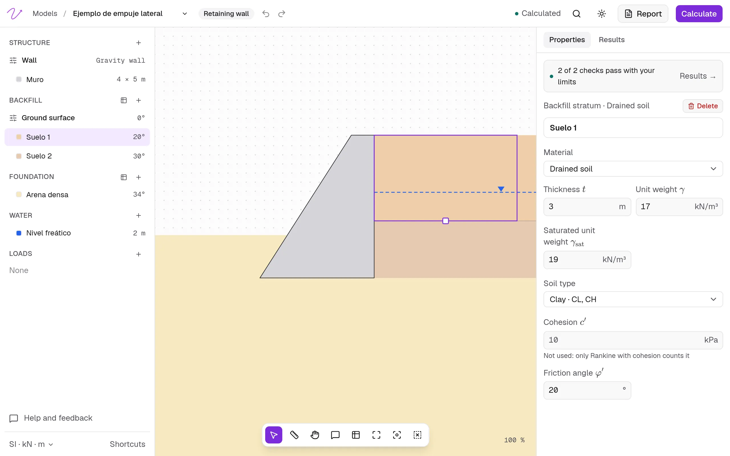
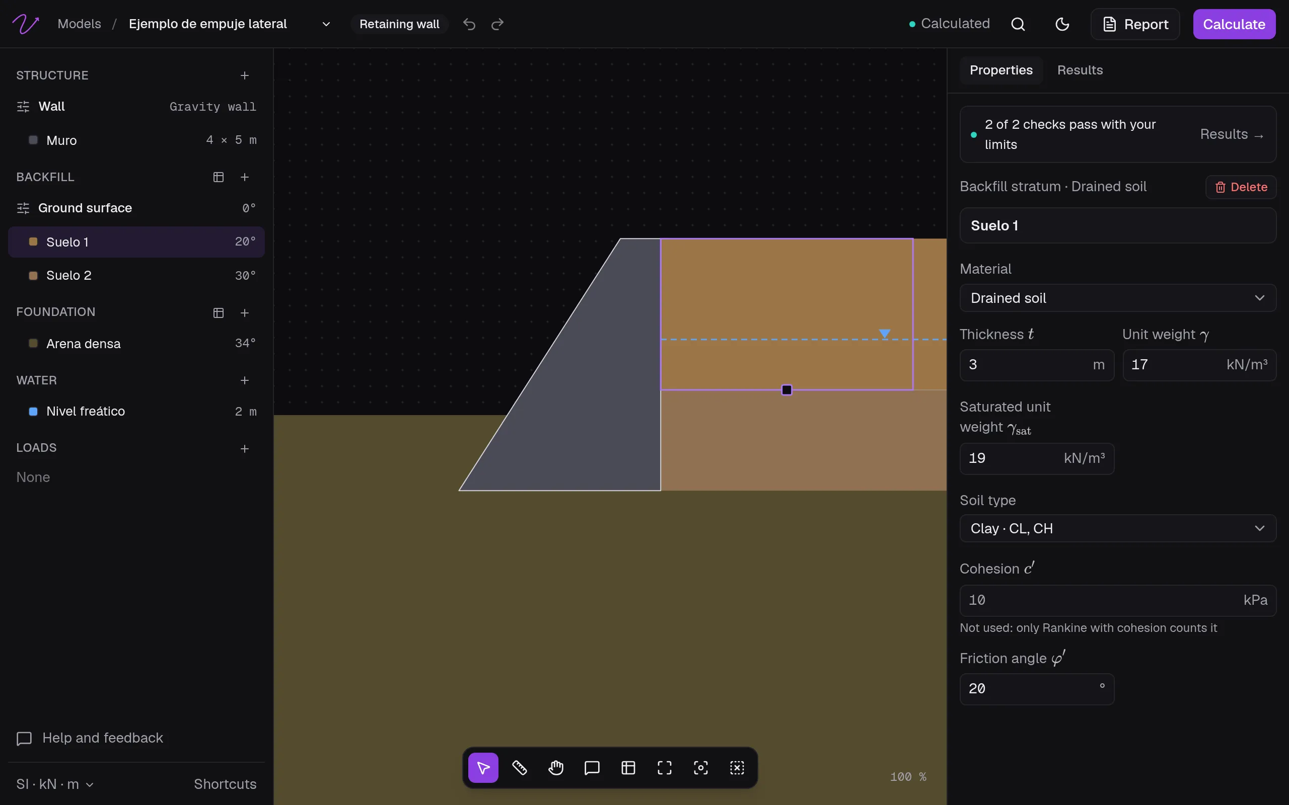
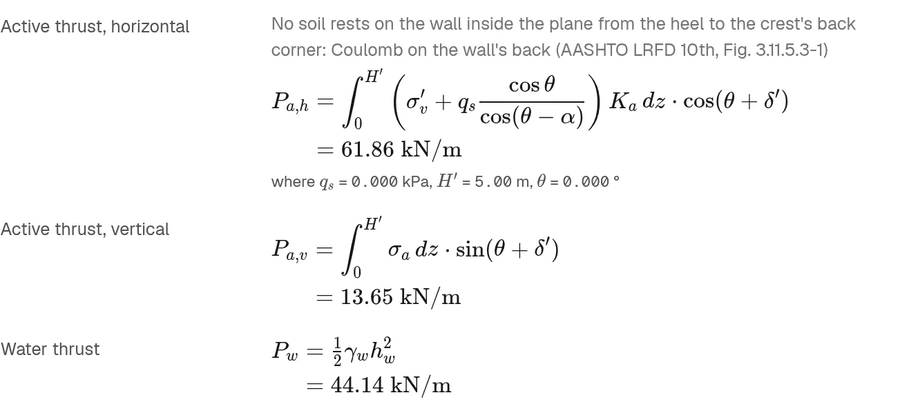
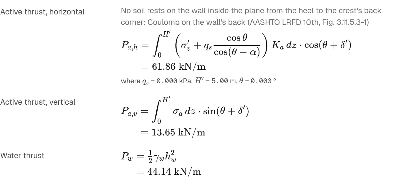
Rischio computes the earth pressure as AASHTO does, without the cohesion term (3.11.5.1): soil 1’s doesn’t reduce it, so there is no tension zone and no crack, and that soil pushes from the surface down. The wall has no heel, so Rischio takes, from the data, Coulomb’s pressure on the wall’s back with a wall friction of half of , and gives = 61.86 kN/m. With Rankine chosen in Earth pressure, the method of this example, it gives = 69.85 kN/m and = 44.14 kN/m: 114.0 kN/m in all, more than the 97.59 kN/m with the crack.
How Rischio handles cohesion, water and surcharges is in Earth pressure. For a single backfill, the lateral earth pressure calculator gives Rankine’s active thrust from the engine, with the water and without the cohesion, and beside it the at-rest and passive thrusts and Coulomb’s coefficients, free and with no account. To carry the thrust into a full wall check (sliding, eccentricity and bearing), see retaining wall design, step by step.
Frequently asked questions
What is the coefficient of lateral earth pressure?
The ratio of the horizontal to the vertical effective stress in the soil. It is when the wall doesn’t move, when it moves away from the soil and when it’s pushed into it. For a sand with , they are 0.500, 0.333 and 3.000.
What is the difference between active and passive earth pressure?
Active pressure is the smallest pressure the soil exerts, reached when the wall moves away from it and a wedge behind the wall slides down. Passive pressure is the largest resistance the soil offers, reached when the wall is pushed into it and a wedge is pushed up. Passive pressure needs five to ten times the movement and is several times larger.
When is at-rest earth pressure used?
For walls that can’t move enough to reach the active state: basement walls held by their floors, culverts, rigid abutments, and gravity walls on rock or on batter piles. A cantilever wall with granular backfill usually moves enough to be designed for active pressure.
Does water increase the lateral earth pressure?
Yes. Below the water table the soil pushes with its submerged weight, which lowers its own pressure, but the water adds its full hydrostatic pressure, , in every direction. In the example, the water alone is 44.15 of the 71.98 kN/m. That’s why retaining walls are drained.
References
- AASHTO (2024). LRFD Bridge Design Specifications, 10th edition. Articles 3.11.1 to 3.11.5.
- Das, B. M., & Sivakugan, N. (2019). Principles of Foundation Engineering.
- FHWA (2006). Soils and Foundations, FHWA NHI-06-089, Volume II, Chapter 10.
- U.S. Army Corps of Engineers (1989). EM 1110-2-2502, Retaining and Flood Walls.