Underpinning Methods: Types, Uses and How to Choose One


A building that was fine for thirty years starts to crack. The cracks are diagonal, they open and close with the seasons, and one corner of the slab has dropped a few centimetres. The structure did not change. What changed is the ground underneath, and the old strip footing is no longer able to keep the wall where it was.
Underpinning is the answer to that problem. It is not a repair product you buy, it is a design exercise: you have to put a new support under a structure that is already carrying load, without letting it move while you do it.
That constraint, more than the soil, is what separates underpinning from ordinary foundation work. This guide covers the methods in use, how to choose between them, and the checks that decide whether a scheme works.
What underpinning is
Underpinning strengthens or extends the foundation of an existing structure so that its loads reach ground that can carry them. There are three ways to close the gap between what the structure demands and what the ground can take:
- Take the load deeper. Extend the foundation down to a competent stratum: mass concrete piers, mini-piles, jacked piles, caissons.
- Spread or redistribute it. Enlarge the loaded area at the same level by widening the footing or casting a raft, or carry the wall on a beam that spans onto new supports.
- Increase the capacity of the ground itself. Grouting, jet grouting and other ground treatment.
Lightening the structure, by removing a storey or changing the use, is the fourth lever, and the one nobody can sell you.
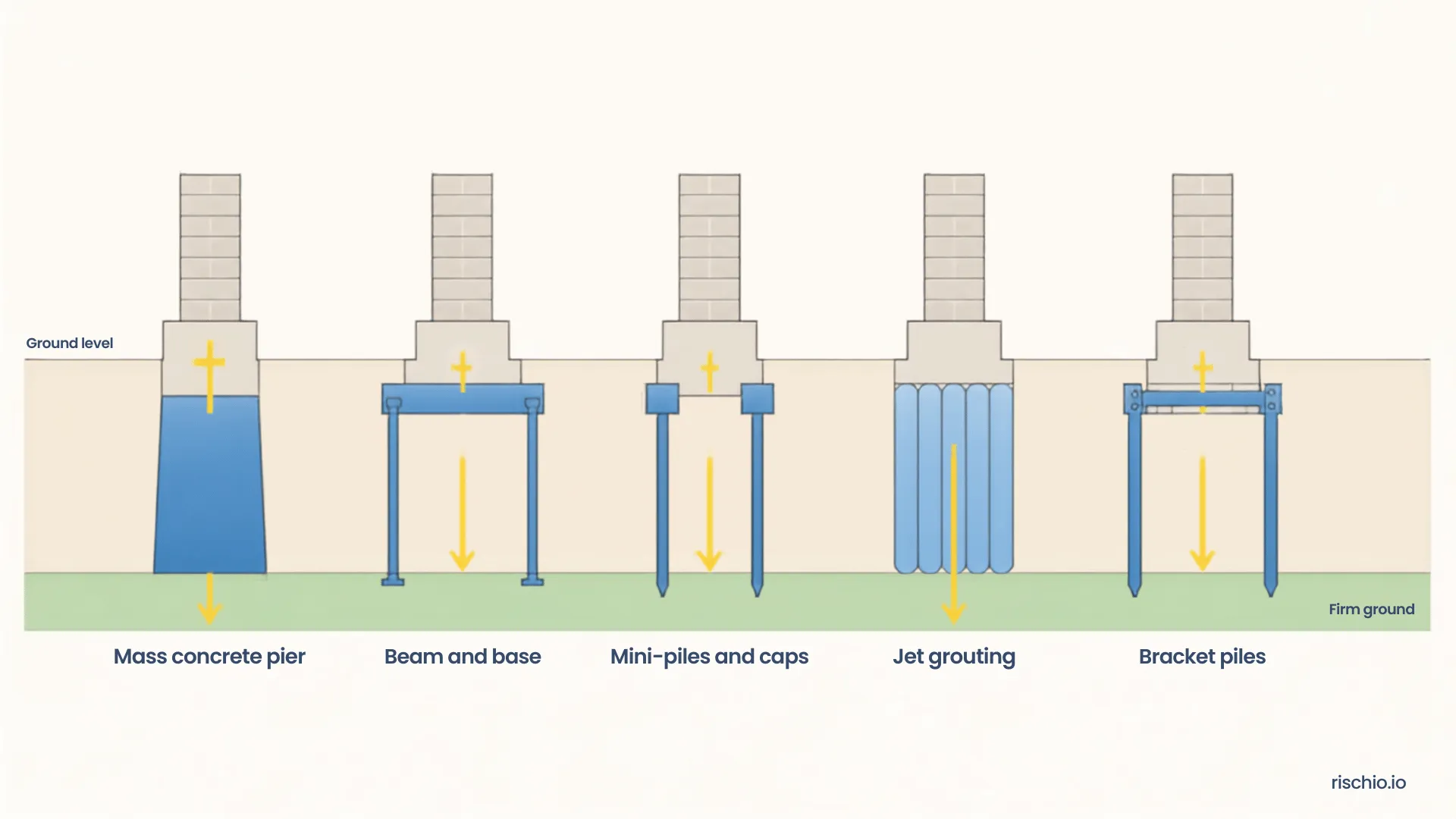
The three are mechanically different. Extending downwards changes where the load ends up; treating the ground changes what the ground can take in place; and a beam-and-pile scheme reaches depth without anyone digging under the wall.
It helps to separate underpinning from two things it gets confused with. Ground improvement treats the soil so the existing foundation can stay where it is, and it works when the problem is the soil mass and not the depth of the footing. Foundation repair covers crack stitching, drainage fixes and re-levelling; those are legitimate, but they do not increase the capacity of the foundation, and they will not stop movement driven by a footing sitting on soft clay.
When underpinning is needed
The usual triggers, roughly in order of how often they appear in practice:
- Differential settlement with structural distress: diagonal cracking, tilting, doors and windows that no longer close, a slab that has dropped relative to the rest of the building.
- Adjacent construction. A new basement, a tunnel, a service trench or an excavation next door removes support from under a footing that never had to cope with it.
- Increased loads. An extra storey, a change of use from housing to storage, new plant or machinery, a heavier cladding system.
- Ground condition changes. A falling water table, tree roots drying shrinkable clay, leaking drains washing fines away, scour, mining or tunnelling subsidence.
- Old or unknown foundations. Shallow masonry strips on variable fill, or footings whose depth and width nobody can confirm.
- A change in the ground level around the building. A new pit, lift shaft or lowered road reduces the confinement the foundation was relying on.
- Deterioration of the foundation itself. Timber piles rotting after a water table drops, reinforcement corroding, sulfate attack on old concrete, mortar washed out of a masonry footing. Here the ground is fine and the foundation is the problem.
- Heave rather than settlement. Removing a surcharge next door, by demolition or excavation, can lift a foundation and crack the structure in a different pattern.
- Vibration. Traffic or construction plant compacting and consolidating loose fill under a footing that was never designed for it.
Two questions decide whether underpinning is actually the right call. First, is the movement finished or ongoing? If the cause has stopped (the drain was repaired, the tree was removed) and the structure is stable, monitoring and crack repair may be enough. Second, is the structure able to take the new support? A wall that has already lost section to crushing or frost damage cannot be relied on to distribute a concentrated pier load.
The constraint that shapes every scheme
You cannot remove support you have not replaced. Everything about underpinning follows from that sentence.
The existing footing is carrying a live load while you dig underneath it. So the work is done in short lengths, in a sequence that always leaves most of the foundation in place and undisturbed:
- Short bays, worked alternately. The wall is divided into bays and only some of them are open at a time. Published good practice for concrete underpinning puts the maximum bay length at 1,50 m, with 1,0 to 1,2 m as the normal figure, and caps the length of wall left unsupported at any moment at around 20% of the total. That last figure has a consequence people miss: a single 1,50 m bay needs a wall at least 7,5 m long to stay inside the limit, which is what forces shorter bays on short walls. The standard sequence works alternate bays, never a run of adjacent pits.
- Temporary support where the footing cannot span. When the existing footing is too weak to bridge an open bay on its own, the load above it is picked up by needle beams, props or brackets before the excavation starts.
- One operation at a time, with the new pier or pile brought into contact with the existing foundation before the next bay is opened.
- Monitoring throughout. Settlement and heave points on the structure, crack gauges, and trigger values agreed before the work starts. If a trigger is reached, the sequence stops and the design is reviewed.
Movement during the works is not a side issue. It is the main risk, and it is what the monitoring is for.
Underpinning methods
Mass concrete (pit) underpinning
The traditional method, and still the simplest to explain. Short bays are hand-excavated under the existing footing and filled with mass concrete, working down to a stratum that can carry the load. Load transfer is by bearing under the new pier, helped by friction along its sides where the ground allows it to be counted.
It works well for depths of roughly one to two and a half metres below the existing footing, in firm ground, with low to moderate loads. Published good practice treats 2,50 m as the limit for a single stage and prefers splitting anything deeper into stages with staggered vertical joints, or switching to piles. It is cheap in materials, needs no plant, and is easy to inspect. The drawbacks are real: it is slow, disruptive, labour-intensive, and it is the wrong answer where the competent stratum is deep, where the water table is high (underpinning in water-bearing granular soils is not recommended without a designed dewatering or ground treatment system), or where the ground would collapse before the concrete goes in.
Two details decide whether it works. The first is the gap between the top of the new pier and the underside of the existing footing: it has to be packed with dry pack, a semi-dry cement-sand mortar, 75 to 150 mm thick, or flood-poured and verified afterwards. Leave that gap soft and the pier never takes load; the wall simply settles onto it. The second is that shaft friction and base bearing mobilise at different displacements, and counting the friction means accepting movement, which is the one thing an underpinning scheme is trying to avoid.
Beam and base (pile and beam)
Instead of extending the foundation downwards, a reinforced concrete beam is cast along the wall and supported on piles or mini-piles placed on one or both sides. The wall load travels through the beam into the piles, which carry it to depth.
It is the method of choice when the wall cannot be undermined at all (party walls, fragile masonry, no access under the footing), when the structure cannot tolerate the open-pit-and-cure cycle that concrete underpinning imposes, or when there is room beside the wall for the piles and the beam. Its weakness is the transfer: the new piles only pick up load as the old footing settles relative to them, so unless the beam is jacked against the existing wall the settlement is shared between the old foundation and the new one.
Mini-pile and pile underpinning
Bored mini-piles, root piles, jacked piles and helical (screw) piles are the modern workhorse. A mini-pile is a small-diameter drilled and grouted pile, typically under 300 mm, and the range used in underpinning runs from about 100 to 300 mm. That means equipment that fits through a doorway and under a low soffit. Load transfer is the same as any pile: shaft friction along the length, plus end bearing where a competent stratum is reached. A single mini-pile carries a modest load next to a large-diameter bored pile; what the method handles well is a high total load carried by a group of them in a space where nothing else fits.
Their main advantage is access and control. Jacked and preloaded piles can be loaded against the structure as they are installed, which means settlement can be measured and partly compensated for, and a preloaded pile is working before it is capped. Mini-piles also suit very deep competent strata and high loads per pile, and they tolerate ground that would collapse a hand-dug pit.
The limits are cost, the need for a properly supervised installation, and the fact that a mini-pile transfers a large load into a small area of the existing footing. That interface has to be checked: the pile cap or bracket bearing on old masonry is a common weak point.
Grouting methods
- Compaction grouting injects a stiff mortar to densify loose granular soil around and below the foundation.
- Permeation (chemical) grouting is for sands, where the grout penetrates the voids and sets around the particles.
- Jet grouting cuts the soil with a high-pressure jet and mixes it with cement to form columns, which can then bear or act as a cut-off.
- Resin injection expands under a slab to lift and re-level it, and fills voids.
Grouting treats the ground rather than the foundation. That makes it attractive where access is impossible, but it comes with two honest caveats: the result is harder to verify than a pile, and the applicability depends entirely on the soil type. Resin injection in particular is marketed for slab lifting, which is a different problem from transferring structural loads that currently have nowhere to go. If the requirement is to move load onto a competent stratum, grouting is rarely the complete answer on its own.
Other approaches you will see
- Bracket piles: piles either side of the wall connected by a bracket that picks up the footing, without undermining it.
- Cantilever and capped pile walls: a row of king piles alongside the wall, carrying it in cantilever or through a capping beam, used where the wall cannot be disturbed.
- Jacking: the structure is supported on jacks and gradually raised back to level, usually combined with a new permanent foundation below.
- Bridge and infrastructure underpinning: pier enlargement, caissons and piled caps, where the constraints are traffic, services and settlement tolerances rather than domestic space.
Comparison
| Method | How load is transferred | Typical use | Main limits |
|---|---|---|---|
| Mass concrete (pit) | Bearing at the base of the new pier, plus friction where it can be justified | Firm ground, competent stratum 1 to 2.5 m below the footing | Slow and disruptive, water table, not beyond about 2,5 m in one stage |
| Beam and base | Concrete beam into piles either side | Moderate loads, shallow footing, limited movement allowed | Needs working space beside the wall |
| Mini-piles and jacked piles | Shaft friction plus end bearing at depth | Deep strata, restricted access, low headroom, high loads | Cost, and the pile-to-footing interface needs checking |
| Grouting | Densifying or cementing the soil, or filling voids | Access impossible, granular soils, void filling, slab lifting | Difficult to verify, strongly soil-dependent |
| Bracket piles and cantilever walls | Piles beside or at the toe of the wall | Walls that cannot be undermined | Large bending moments, space for the piles |
One thing the table cannot show is verification. Piles can be load-tested or preloaded, grouting cannot, and that difference should weigh in the choice.
Installed cost is driven less by the method than by access, depth and the amount of temporary support the structure needs. Two similar houses on the same street can differ by a factor of two in cost because one has a basement next door and the other does not.
How to choose a method
Work through these in order; each one removes options:
- Depth to a competent stratum. Shallow and reachable: mass concrete competes. Deep or uncertain: piles and mini-piles.
- Load and eccentricity. The heavier and more eccentric the wall load, the more the scheme depends on piles rather than bearing.
- Condition of the existing foundation. Masonry that is already crushing cannot distribute load into a small new pier without a beam or a cap.
- Access and headroom. Inside a building or against a party wall, the equipment choice decides the method, not the soil.
- Groundwater. Water in a hand-dug pit is a safety and a quality problem. Below the water table, driven or bored piles in a cased hole are usually preferable.
- Vibration and noise limits. Jacked and bored piles are quieter than driven ones, which matters next to hospitals, labs and historic structures.
- Movement that the structure can tolerate. This sets the monitoring plan and whether preloading or load testing is required.
- Verification. A method whose capacity can be tested or preloaded gives you evidence. For micropiles that is not optional: the FHWA reference manual requires at least one pre-production verification load test on every project, taken to no less than 2,0 times the design load. Grouting offers no equivalent, which is a reason to treat it as a complement rather than a substitute.
Worked example: the checks that decide
A two-storey masonry building on a 0.6 m wide strip footing at 1.0 m depth. The geotechnical report gives an allowable bearing pressure of 90 kPa at that level and 200 kPa at 2.5 m depth. The wall load is 90 kN per metre of wall. The building is settling.
| Input | Value |
|---|---|
| Wall load (dead + live), | 90 kN/m |
| Existing footing width, | 0.60 m |
| Existing footing depth below ground level | 1.00 m |
| Existing footing thickness | 0.20 m |
| Allowable bearing at 1.00 m | 90 kPa |
| Allowable bearing at 2.50 m | 200 kPa |
| Unit weight of mass concrete | 23 kN/m³ |
Why it is moving. The pressure under the existing footing is
The footing is asking the soil for 150 kPa where only 90 kPa is available. Nothing about the wall explains the cracks; the numbers do.
Check 1: the permanent underpinning. Bays 1.50 m long are underpinned in an alternating sequence, each bay becoming a mass concrete pier 0.90 m wide from the new founding level at 2.50 m up to the underside of the existing footing.
The new pier uses about two thirds of the available bearing pressure, which leaves margin for the eccentricity and for the load that will transfer from the adjacent bay later.
Note what the comparison assumes. The check is on gross pressure, pier weight included, against the allowable value from the report, which is the conservative reading; a net check would deduct the overburden removed at the new founding level and leave more margin. Whichever is used, it should be stated, and it is worth confirming that the allowable value applies to a 0,90 m wide element: allowable bearing pressure depends on the width of the loaded area, and the new pier is wider than the footing it replaces.
Check 2: the bay that is open. While that 1.50 m bay is being dug, the wall above it has to be carried. If the existing footing were relied on to act as a beam, the bending moment would be
A 0.60 m wide footing 0.20 m thick has an elastic section modulus of
and would therefore develop a flexural stress of
Compare that with what the material can take. Take a modest C20/25 concrete: mean tensile strength 2,2 MPa, and a flexural tensile strength for a 200 mm deep section of about 3,1 MPa. The applied 6,3 N/mm2 is roughly double, so the footing cracks and cannot be assumed to carry the open bay. The check uses unfactored loads, ignores the footing’s own weight inside the span and any surcharge on it, and is a screening calculation for the temporary condition rather than an ultimate limit state check — but the conclusion is robust, because an old masonry or lean-concrete footing would be weaker still.
That is what justifies temporary support: needle beams pick up the wall on both sides of the bay before excavation starts. With one needle at each end of the bay, the reaction is half the 135 kN, so 67,5 kN per needle, and the needle has to span the pit and bear or prop outside it. That brings in a third check that is easy to forget: the ground beside the pit, already disturbed by the excavation, has to carry the needle reaction and the load that the open bay redistributes onto the neighbouring foundation.
Skipping this check is one of the classic ways an underpinning job goes wrong. The permanent design is fine, and the wall cracks while the second bay is open.
Checking the scheme before anything is dug
Underpinning design is iterative. Method, bay length, founding depth and temporary support all interact, and moving one changes the others, so the numbers get run several times before a single pit is opened. Two of the checks in the example above are the kind that pay to repeat: the pressure under the new pier, and the pile capacity if the scheme goes the mini-pile route. Rischio’s deep foundation tools cover pile and foundation capacity checks, and the gross versus net bearing pressure distinction is worth reading before putting the first number into them, because it is the one that gets misapplied most often.
Monitoring and control
The design sets the movements, the site measures them:
- Settlement and heave points on the structure and on adjacent buildings, read before work starts to establish a baseline. A dilapidation survey of the neighbours, agreed before anyone breaks ground, is what keeps a crack from becoming a claim.
- Crack gauges across the significant cracks, so opening and closing is measured rather than argued about.
- Water levels in piezometers wherever the works involve dewatering or a shallow water table: losing water is the fastest way to induce settlement, and it happens under your own site as easily as next door.
- Inclinometers or tilt measurement on adjacent retaining walls and slopes, where settlement alone does not describe the risk.
- Ground vibration monitoring where piling or compaction happens next to sensitive structures.
- Trigger values with a named response and a time limit: who reads the data, what movement triggers it, and how long until the works are stopped and the design reviewed.
- A defined period of reading after the works finish, because consolidation under the new foundation continues long after the props come out, and that is when a claim is either supported or not.
For jacked and preloaded piles, load and settlement are recorded as each pile is installed, which turns the installation itself into the verification of capacity.
Common mistakes
- Opening too long a bay, or too many at once. The most frequent cause of damage during underpinning, and it is a sequencing failure, not a soil surprise.
- No temporary support. Assuming the existing footing will span the bay without checking it, as the example above shows.
- Stopping short of competent ground. The new pier or pile founded in the same soft layer that caused the settlement, only deeper.
- Ignoring the footing-to-pier interface. A concentrated load onto already cracked masonry crushes it. Beam, cap or spread it.
- Not controlling water. An unmanageable inflow in a hand-dug pit means loss of fines under the adjacent footing, and a much bigger problem than the one you were hired for.
- Underpinning one side of a shared wall. Load paths cross property boundaries.
- Confusing grouting or resin with structural underpinning. They solve different problems, and the evidence of capacity is not equivalent.
- A soft interface. The pier or pile cap not packed tight against the existing footing. It is a quality failure rather than a design one, and it produces immediate settlement.
- Checking the new element and not the ground beside the pit. The excavation redistributes load onto the neighbouring foundation, and the props and needles need bearing capacity too.
- Starting before the cause is established. Underpinning treats the symptom; if a drain is still leaking or a tree is still extracting water, the movement continues around the new foundation.
- Forgetting the temporary condition of the new elements. Mass concrete piers standing exposed in a deep pit carry horizontal loads while the excavation is open, and they need propping until they are backfilled.
- Ignoring cumulative settlement across stages. Each load transfer moves the structure a little; individually negligible and collectively not.
- No consents. Party wall agreements and approvals for working under or beside a neighbour’s property have their own timescale and their own surveyor.
- No monitoring. Without measurements, the first sign of trouble is the crack that appears in the neighbour’s wall.
FAQ
How much does underpinning cost? Cost is driven by the number of piers or piles, the depth to competent ground, access and the temporary support the structure needs. It is priced per unit of installed quantity, so anyone quoting a figure per metre of wall without a ground investigation is guessing. The useful questions to ask are how many units, to what depth, with what temporary works, and what the verification is.
How long does underpinning take? Mass concrete bays are slow: excavation, inspection and concrete curing are sequential, and only part of the wall can be open at a time. Mini-pile schemes install faster per unit but need a beam and caps afterwards. Sequencing, not the method, usually sets the construction programme. The works are rarely the long pole in the project, though: third-party consents, party wall agreements and approvals for working under or beside a neighbour’s property can take longer than the construction itself, so they belong at the start of the programme.
Can the building stay occupied? Yes, in most cases. Mini-pile and beam-and-base schemes let the work be carried out from small access pits along the wall line instead of an open excavation under the whole structure, and that is why they are popular in occupied buildings. It is not free: expect vibration, noise, dust, and pits and props occupying floor area for weeks, plus agreements with the occupants and, for shared walls, with the neighbour. Those constraints feed straight back into the method choice.
How do I know whether underpinning is needed at all? An investigation that establishes the soil profile, the founding depth of the existing foundation and the cause of the movement. If the cause has stopped and the structure is stable, monitoring may be the right answer. If the footing is bearing on ground that cannot carry the load, no amount of crack repair will fix it.
Does underpinning always stop the movement? It stops movement caused by the foundation. It does not fix damaged drains, tree-related clay shrinkage, or continuing subsidence from a source nobody identified. Those have to be dealt with separately, and the order matters.
Conclusion
Underpinning is a load-transfer problem with a sequencing constraint, and the methods differ mainly in how deep the load has to travel and how much access you have. Mass concrete bays remain the simplest answer where competent ground is close to the surface. Mini-piles and jacked piles handle depth, restricted access and load with more control, at a higher cost and with a load interface that has to be detailed properly.
The part that rewards care most is neither of those. It is the sequence and the temporary support: the check that the existing footing will not span the bay you are about to open, and the monitoring that tells you when to stop. A scheme that gets the permanent foundation right and the sequence wrong still damages the building.
References
- Temporary Works Forum / ASUC (2023). Underpinning: Good practice guidance, TWf2023:02. The practical figures in this article for bay length, staged depth, dry pack and support of excavations come from this guide.
- EN 1997-1:2004+A1:2013, Eurocode 7: Geotechnical design, Part 1. The second generation (BS EN 1997-1:2024) is published, with the first-generation British adoption withdrawn on 30 March 2028, so projects in the UK are in transition and the contract should say which one applies.
- BS 8004:2015+A1:2020, Code of practice for foundations. BSI.
- EN 1992-1-1:2004, Eurocode 2: Design of concrete structures, Part 1-1, used here for the flexural tensile strength comparison.
- FHWA-NHI-05-039 (2005). Sabatini, P. J., Tanyu, B., Armour, T., Groneck, P. and Keeley, J., Micropile Design and Construction — Reference Manual for NHI Course 132078. Federal Highway Administration / National Highway Institute.
- FHWA-NHI-16-027 (2017). Ground Modification Methods Reference Manual, Volume I. Federal Highway Administration.
- ACI CODE-318-25, Building Code for Structural Concrete; and ACI CODE-562-25, Assessment, Repair and Rehabilitation of Existing Concrete Structures, which is the relevant one for work on an existing building.
- Tomlinson, M. and Woodward, J. (2014). Pile Design and Construction Practice, 6th edition, CRC Press.
- Institution of Structural Engineers (2000). Subsidence of low rise buildings, 2nd edition.